8.3. Variable Flux
The “Variable-Flux” boundary condition is used to specify variable-flux boundary conditions. The variable-flux boundary is used to simulate a domain of large extent without the need to greatly extend the model domain. The “Variable-Flux” option applies the analytical solution for a semi-infinite aquifer to the boundary of the modeled flow domain. To ensure that the variable-flux boundary conditions are implemented properly, the actual boundary of the model domain should be far enough from any hydraulic stress so that effects from these hydraulic stresses do not reach the variable-flux boundary condition.
To add a variable-flux boundary condition to the model, add a “2D Contour” or “3D Contour” plot item to the View Pane. Next, toggle to the desired node layer using the “Layer” attribute of the “2D Contour” or “3D Contour” plot item. Use the “Select” tool from the toolbar to select the nodes on the edge of the model domain where the variable-flux boundary condition is to be assigned. When the nodes are selected, press the [Enter] key to open the “Assign Properties for Nodes” dialog box. Check the radio button next to “Assign to Variable-Flux Boundary”; this will activate additional options. The additional options are “All nodes in between (counterclockwise) are selected,” which will assign the variable-flux boundary condition to all the perimeter nodes of the model domain between two selected nodes in a counterclockwise direction, and “From Current Layer # To,” which will assign the variable-flux boundary condition from the currently selected layer to the chosen layer. The nodes that have a variable-flux boundary condition assigned can be modified using the “Variable-Flux Boundary” dialog box under the “BCs” drop-down menu found on the Main Menu banner at the top of the screen. The “Variable-Flux Boundary” dialog box is shown in Figure 8.10. The information that can be modified for the variable-flux boundary condition is described below.
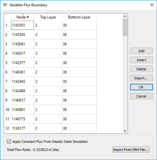
Figure 8.10 The “Variable-Flux Boundary” dialog box
Node #: The uppermost node number of the variable-flux boundary condition.
Top Layer: The uppermost layer number in which the variable-flux boundary condition begins.
Bottom Layer: The layer number in which the variable-flux boundary condition ends.
Option to Apply Constant Flux from Steady-State Simulation: Note that
this requires a .DRN file from a steady-state simulation. To import the
.DRN file, click “Import from DRN File” and navigate to the location
of the .DRN file using the “Open Variable Flux File” window.
| Was this helpful? ... | Itasca Software © 2025 | Updated: Sep 23, 2025 |
