8.4. Pumping Well
This option is used to specify values for source/sink terms modeled as pumping wells. When “Pumping Well” is selected from the “BCs” drop-down menu found on the Main Menu banner at the top of the screen, the dialog box shown in appears. In MINEDW, there are three options available for pumping wells. Pumping wells can be introduced to the model by defining pumping rates, specified heads, or pumping rates with an LPE (”Pumping Rate,” “Specified Head,” or “Pumping with LPE”).
Pumping wells can be added to the model by importing a previously created “pumpwells.dat” file. To import the file, simply click on “Import” and, using the “Open Pumping File” window that opens, navigate to the location of the “pumpwells.dat” file, select it, and click “Open.” Note, if there are any existing wells in the “Pumping Well” dialog box, they will be overwritten and replaced with the contents of the “pumpwells.dat” file.
Pumping wells can be created by MINEDW based on x, y, and z data
in a .DAT file:
File should contain three columns of x, y, and z data corresponding to pump locations
Click the “Create” button
In the “Select DAT file” window, navigate to the directory containing the location data file
Select the file and click “Open”
MINEDW will select the finite-element node at each specified x, y, and z location
If no node exists at a location, MINEDW will move the closest node to that location
Use the “Pumping Well” dialog box to modify screen intervals, pumping rate, and pumping well type
Another option for adding pumping wells to the model is to select the nodes where pumping wells are to be simulated using a “2D Contour” or “3D Contour” plot item and the “Select” tool and then choosing “Add to Pumping Wells” in the “Assign Properties for Nodes” dialog box as described in Nodes and Elements. The user must take care to select the correct node layer in the “3D Contour” plot item where the pumping well is to be simulated. For example, if the user inadvertently uses the top node layer, the pump or sink will be simulated at the top of the model domain and will likely be ineffective at removing groundwater from the system. Also, the user will have to specify the screen intervals, pumping well type, and pumping rates in the “Pumping Well” dialog box after adding pumping wells using this method.
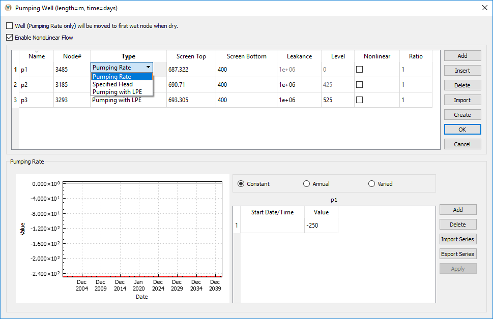
Figure 8.11 The “Pumping Well” dialog box
In MINEDW, a “Pumping Rate” well allows the user to specify the exact pumping rates they want to use for a model simulation. This type of pumping well is useful for a model calibration simulation when field-recorded pumping-rate data are available. As mentioned above, using a “Pumping Rate” well may dry out the groundwater system within the vicinity of the pumping well if the pumping rate is too large or the hydraulic conductivity values assigned are too low. MINEDW will print a warning to the “MINEDW.err” file if this occurs during a model simulation, but it is the user’s responsibility to check this file, as MINEDW does not stop running when this occurs.
“Pumping Rate” wells have the option to move to the first wet node if the node where the pump is located becomes dry. This option should be exercised with care, as MINEDW will continue to move the pumping node lower, which may result in the pumping node moving to the bottom of the model domain. A pumping node located at the bottom of the model domain (on a no-flux boundary) is incorrect, as pumping stresses should not propagate to a boundary condition. If the user wishes to use this option, they are advised to check that pumping stresses never intersect other user-defined boundary conditions as the pumping node moves downward. To activate this option, check the box next to “Well (Pumping Rate only) will be moved to first wet node when dry,” and the nodes defined as a “Pumping Rate” well will be moved to the next wet node when the pumping nodes become dry.
“Enable Nonlinear Flow” enables nonlinear flow for pumping wells. If this option is enabled, the “Nonlinear” field will become visible in the “Pumping Well” dialog box. Each well where nonlinear flow is to be simulated will need to be enabled individually. The required information for the “Pumping Well” dialog box is described below.
Name: Name of the pumping well.
Node #: Identity of node in the pumping data set.
Type: Switch for the type of pumping well (options available are “Pumping Rate,” “Specified Head,” and “Pumping with LPE”).
Screen Top: Elevation of screen top (in meters or feet).
Screen Bottom: Elevation of screen bottom (in meters or feet).
Level: Defined as either the LPE or the specified head depending on the type of well defined.
Nonlinear: Enables nonlinear for the selected well.
Ratio: The ratio to use for nonlinear flow.
After selecting a pumping well in the “Pumping Well” dialog box, the time-series menu becomes active, as shown in Figure 8.11. In this menu, the user can import time-series data for each type of pumping. The three options are “Constant,” “Annual,” and “Varied” (as described in Time-Series Data).
“Specified Head” pumping wells are analogues to drains because they can be used to achieve a specific-head value within the groundwater system surrounding the well by extracting the necessary amount of water. Unlike drains, however, no leakance values need to be defined for “Specified Head” wells. “Specified Head” wells are often used in predictive simulations to evaluate dewatering requirements. When used for this purpose, the objective is to achieve the dewatering needs of the project and quantify the amount of water that will need to be extracted to achieve the dewatering target. After quantifying the dewatering requirements, the physical well can be designed to achieve the simulated pumping rates. However, if a “Specified Head” well is used to simulate an existing well, it would be prudent to ensure that the calculated pumping rates of the simulated well do not exceed the maximum pumping rate of the physical well.
Finally, the “LPE” well, which is typically used in a predictive simulation, is defined by assigning a pumping rate to the well and the LPE. The LPE allows the user to specify the minimum allowable head in a well. If the head within the well is equal to or less than the LPE, the pumping rate will be reduced in order to maintain the LPE until the head exceeds the LPE. If the head exceeds the LPE, then the “LPE” well will pump at the rate defined by the user. This feature allows the user to ensure that a proper water-column height is maintained or that the groundwater system does not become dry due to either high pumping rates or low permeability. If an “LPE” well is used during calibration, the user should compare pumping rates printed in the .FLW file with those that were assigned. If rates in the .FLW file are less than the rates that were assigned, this may indicate that the hydraulic parameters assigned to the model are too low. Conversely, assigning maximum pumping rates to “LPE” wells during predictive simulations allows the user to determine the maximum pumping rates that can be sustained with the assigned hydraulic parameters.
| Was this helpful? ... | Itasca Software © 2025 | Updated: Sep 23, 2025 |
