8. Boundary Conditions
A groundwater flow model must include a suitable set of boundary conditions to define the mathematical problem being solved. In MINEDW, six types of boundary conditions are available:
Constant head
Variable flux
Pumping well
Rivers
Recharge
Evaporation
The first four (constant head, variable flux, pumping wells, and rivers) are applied to nodes, whereas recharge and evaporation are applied to elements.
To define the boundary conditions, select “BCs” from the Main Menu banner, then choose the appropriate boundary-condition type from the “BCs” drop-down menu (see Figure 8.1). Each boundary-condition type requires a different set of parameters, as described below. (Note that the data-input windows have similar features and functionality).
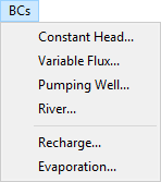
Figure 8.1 The “BCs” drop-down menu
Boundary conditions are assigned using node or element plot items. Use the “Assign Properties for Nodes” dialog box to assign “Constant Head & Drain,” “Variable-Flux,” and “Pumping Well” boundary conditions. The “Assign Properties for Nodes” dialog box shown in can be accessed by adding a “2D Contour” or “3D Contour” plot item from the “Control Panel” Pane. Select the desired nodes and then press Enter to bring up the dialog box.
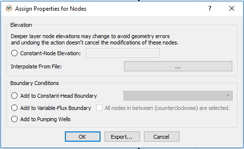
Figure 8.2 The “Assign Node Properties” dialog box
Recharge and evaporation boundary conditions can be applied to the model using a “2-D Plane” plot item. To assign recharge or evaporation to the model, access the “Select Recharge Zone” or “Select Evaporation Zone” dialog box, shown in Figure 8.3 and Figure 8.4, respectively, by adding a “2-D Plane” element plot item from the “Control Panel” and then selecting the desired “Color By” attribute, “Recharge,” or “Evaporation.”
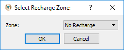
Figure 8.3 The “Select Recharge Zone” dialog box
Next, select the desired elements using the methods described earlier, press Enter, and the “Select Recharge Zone” or “Select Evaporation Zone” dialog box appears. Assigning recharge and evaporation boundary conditions is described in more detail in Recharge and Evaporation.
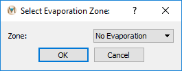
Figure 8.4 The “Select Evaporation Zone” dialog box
All boundary conditions can be applied as time-varying conditions. The implementation of these time-varying conditions is described in Time-Series Data below, which is followed by a description of each type of boundary condition available in MINEDW.
The following sections provide detailed information about configuring and implementing each type of boundary condition in MINEDW. Begin with the time-series data section to understand how temporal variations are defined, then explore the specific boundary condition types relevant to your model.
| Was this helpful? ... | Itasca Software © 2025 | Updated: Sep 23, 2025 |
