8.2. Constant Head
The “Constant Head” option is used to implement specified-head boundary conditions, which can take the following forms:
The constant-head boundary is invariant with time (constant time series).
The constant-head boundary varies with time in accordance with a specified hydrograph, which is input in the form of a table of the hydraulic heads at specified times (varied time series).
The constant-head boundary varies annually in accordance with a specified hydrograph, which is input in the form of a table of the annual hydraulic heads (annual time series).
The boundary condition is simulated as a drainage node. A drainage node is the condition in which water can discharge from—but not into—the groundwater system. This condition can exist if groundwater can discharge to a subsurface drainpipe, to the pit wall, or to underground workings. Time-series data can also be applied to drain nodes and represent the time-varying head (drain level) at the drain node. Ensure that drain levels are not lower than the elevation of the node that the drain is defined on and that drain levels do not exceed the elevation of the node directly above the drain. If this occurs, MINEDW will provide the user with a warning and the drain node will not be simulated properly.
“Constant Head” nodes and “Drain” nodes can be deactivated (turned off) at any time during the simulation by entering the appropriate date and a value of “-99999999” in the time-series window. Entering a value of “0” for either boundary condition will not deactivate the boundary condition, but rather, it will assign the boundary condition a constant head or drain level of 0 m.
When “Constant Head” is selected from the “BCs” drop-down menu, the dialog box in appears. The required data for a constant-head boundary condition are described below.
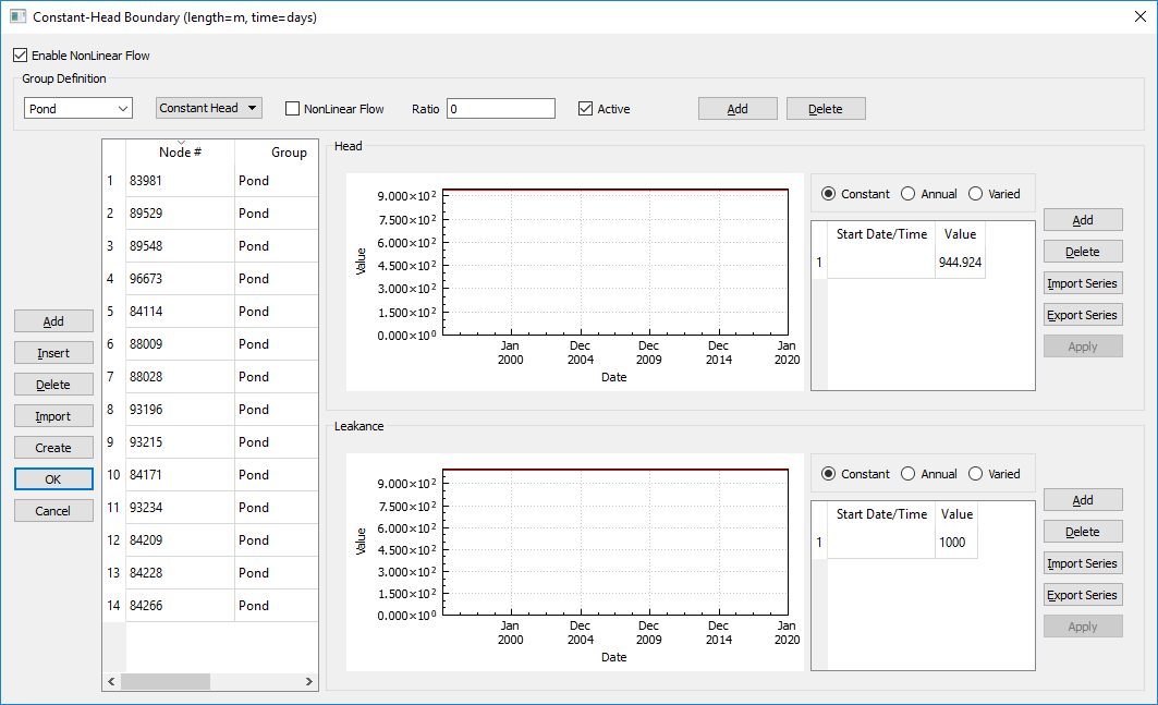
Figure 8.7 The “Constant-Head Boundary” dialog box
- Enable Nonlinear Flow:
Option to simulate nonlinear groundwater flow at drains and constant heads. If enabled, the user has the option to enable nonlinear flow for every group. If the user chooses to use nonlinear flow, they must define the nonlinear flow ratio. The nonlinear flow ratio is the ratio of Non-Darcian to Darcian flow; a value of 0 indicates the flow is completely Darcian.
- Group Definition:
The “Group Definition” portion of the “Constant-Head Boundary” dialog box allows the user to define groups of constant-head or drain boundary conditions.
Constant-head or drain groups are added by clicking the “Add” button at the top of the dialog box. With the drop-down box (Figure 8.7), next to the “Activate” checkbox select either “Constant Head” or “Drain” to define the type of boundary condition thegroup will be. Each group added will appear in the “Groups” drop-down list shown in Figure 8.8. The names of each group can be modified as desired, as shown in Figure 8.8. Use the “Delete” button to remove unneeded group names, and check or uncheck the “Active” box to activate or deactivate constant-head and drain groups. If nonlinear flow is to be simulated for the constant-head or drain group, check the box next to “NonLinear Flow” and input a value for “Ratio.”
Constant-head groups allow the user to group constant-head nodes or drain nodes together to calculate the flux for each constant-head group (e.g., a set of sub-horizontal drain holes or a regional constant-head boundary). Output flux with respect to time is calculated for each group and is output in the flow file (.FLW).
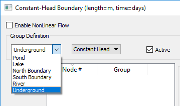
Figure 8.8 The “Define Group for Constant Heads and Drain Nodes” dialog box
- Node #:
The node number where the constant-head boundary condition is defined.
- Group:
The constant-head group to which a particular node is assigned. Using the drop-down box below “Group Definition,” the user can select any of the constant-head groups.
- Type drop-down list:
This drop-down list is located to the right of the “Group” drop-down list. It is used to specify the type of constant-head node (constant-head or drain node).
- Head:
Constant-head elevation; if constant, varied, or annual, constant-head elevations can be edited in the time-series data box on the right side of the “Constant-Head Boundary” dialog box.
- Leakance:
Leakance factor (square meters per day [m2/day] or square feet per day [ft2/day]). Leakance factors can be “Constant,” “Annual,” or “Varied.” These options are available in the lower time-series data box on the right side of the “Constant-Head Boundary” dialog box.
Once the constant-head groups are defined, constant-head nodes can be assigned in several different ways. First, a “2D Contour” or “3D Contour” plot item can be added and nodes can be selected (as described in Nodes and Elements) to bring up the “Assign Properties for Nodes“”””””” dialog box shown in Figure 8.9. Here, the boundary conditions for the selected nodes can be modified. Once the “Add to Constant-Head Boundary” button is clicked, the user has the option to select the constant-head group from a drop-down menu as well as the layers to which the constant head will be applied, with the top layer being the one selected in the “Plot Item” attributes menu.
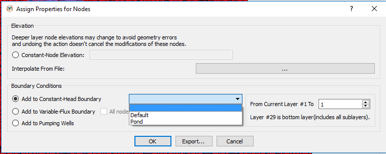
Figure 8.9 The “Assign Properties for Nodes” dialog box and constant-head groups
Additionally, constant-head nodes can be created in the “Constant-Head Boundary” dialog box (see Figure 8.7) in several different ways. First, a “chead.dat” file from a previous model data set can be imported using the “Import” button. Also, constant-head nodes can be defined using a .BLN file and the “Create” button. This function can be used to quickly create sub-horizontal drain holes, which are commonly used in mining operations to minimize pore pressures in the pit wall. To use this function, click “Create,” and a “Select BLN File” window opens. Select the .BLN file representing the sub-horizontal drain hole and click “OK.” Drain nodes will be created at nodes close to the .BLN file. The drain elevation assigned by default to each of the drain nodes will be the node elevation. Finally, constant-head nodes can be created manually by entering the required parameters in the table.
Parameters of the constant-head nodes can be edited by group using the “Group” drop-down box. When the name of each constant-head group is selected, the nodes composing the group appear in the window below the drop-down box. After selecting the desired group, the constant-head nodes composing the group can be selected by clicking in the upper left-hand corner of the table. Once the nodes in the desired group are selected, they may be edited as a group by entering values for “Head” or “Leakance” in the appropriate time-series window.
When a “Constant Head” or “Drain” record is selected, the time-series dialog becomes active. In the time-series dialog, the user is able to import time-series data for constant heads or drain nodes. The three options are 1) “Constant,” 2) “Annual,” and 3) “Varied.” These options are explained in the Time-Series Data section.
| Was this helpful? ... | Itasca Software © 2025 | Updated: Sep 23, 2025 |
