8.7. Evaporation
The “Evaporation” boundary condition is used to simulate the discharge of groundwater from a shallow water table due to evapotranspiration from vegetated areas or evaporation from a bare-soil area. In this option, the evapotranspiration rate depends on the local depth to the water table, the extinction depth, the potential evapotranspiration rate, and the size of the evaporation zone. The simulation assumes that discharge is linearly related to the depth from just below the ground surface down to the water table. The linear relation holds until a maximum depth is reached; this is the extinction depth. At the extinction depth, evapotranspiration (or evaporation) ceases, and its value is zero for any depth greater than the extinction depth.
When “Evaporation” is selected from the “BCs” drop-down menu on the Main Menu banner found at the top of the screen, the dialog box shown in appears. The required information for evaporation zones is described below. Similar to recharge zones, evaporation parameters must be defined prior to applying them to the model.
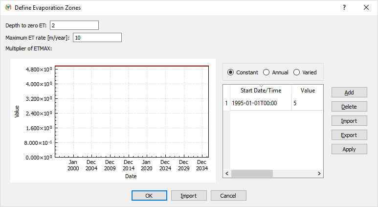
Figure 8.18 The “Define Evaporation Zones” dialog box
Depth to Zero ET: Extinction depth (depth below which there is zero evapotranspiration).
Maximum ET Rate: Maximum evapotranspiration rate (m/yr or ft/yr).
Multiplier of ETMAX: ETMAX is defined as the maximum evapotranspiration rate. This defines the multiplication factor of maximum evaporation for the time step. The multiplier of ETMAX can be defined as time-series data. The three options are constant, annual, and varied. Each is explained in the time-series data section (Time-Series Data).
After defining the evapotranspiration zones, the plot item “2-D Plane” should be selected from the list provided in the “Control Panel.” In the “Color By” attribute, select “Evaporation.” Now, using the “Select” tool (see Nodes and Elements), elements can be selected and the newly created evaporation zones can be applied to the elements.
| Was this helpful? ... | Itasca Software © 2025 | Updated: Sep 23, 2025 |
