9.4. Underground Mining
9.4.1. Zone of Relaxation for Caving
In MINEDW, the time-varied hydraulic conductivity related to the displacement of rock caused by underground mining can be simulated.
To create this hydrogeologic zone, select “Zone of Relaxation for Caving” from the “Mining” menu on the Main Menu banner. The “Create Zone of Relaxation for Cave Zone” dialog box appears (see Figure 9.19). Information required for creating this hydrogeologic zone is described below.
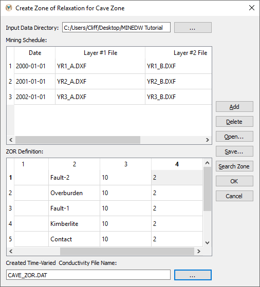
Figure 9.19 The “Create Zone of Relaxation for Cave Zone“ dialog box
- Mining Schedule:
The spatial extent of displaced rock over time due to block caving, which includes the date when the mining phase begins and the file names of 3-D .DXF files delimiting the extent of the inner and outer ZOR layers for the mining phase.
- ZOR Definition:
The factors by which hydraulic conductivity increases/decreases for each hydrogeologic zone that is displaced by caving.
Date and file name information can be entered manually in the “Mining Schedule” window or automatically using a mining schedule file. If “Mining Schedule” information is to be entered manually, enter the date when the first mining phase will begin and then enter the file name of the .DXF file defining the inner ZOR layer in the column labeled “Layer #1 File.” Next, enter the file name of the file defining the outer ZOR layer in the column labeled “Layer #2 File.” Click “Add” on the top right of the dialog box to add a new entry, and repeat the steps described above until the ZOR for caving is completely defined. To use a mining schedule file to enter information into the “Mining Schedule,” click “Open…” and locate the mining schedule file. Select it and then click “Open” in the “Open Caving ZOR File” dialog box. Note that MINEDW only supports two ZOR layers for caving, unlike the option for open pits, in which the user can define as many ZOR layers as desired.
After entering the necessary data, click “Search Zone.” The relevant hydrogeologic zone appears. Enter the factors by which hydraulic conductivity will change for each ZOR layer under the columns labeled “Layer #1” and “Layer #2.”
Enter the file name of the cave-zone ZOR file to be created in the box at the bottom of the “Create Zone of Relaxation for Cave Zone” dialog box and then click “OK.” To assign the created time-varied conductivity file for a cave zone to the model, please see the following section.
9.4.2. Dewatering and Underground Mining
The “Dewatering and Underground Mining” menu is used to assign the underground ZOR mining file to the model and to define groundwater recovery in the mined area at the end of mining. The drop-down box at the top of the dialog box contains a list of underground mines already defined (this list may be blank if none have been defined). The “Add” and “Delete” buttons to the right of the drop-down box are used to add or delete mines from the model. The “Dewatering and Underground Mining” dialog box is divided into three tabs: 1)“General,” 2) “ZOR,” and 3) “Recover” (see Figure 9.20), which are explained in the following sections.
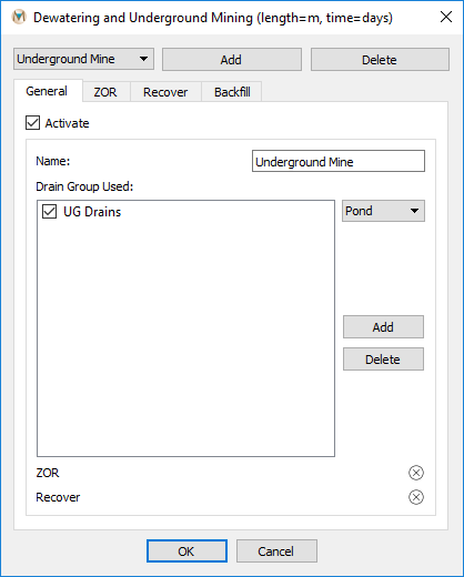
Figure 9.20 The “Dewatering and Underground Mining“ dialog box
The following options are available in the “General” tab:
- Activate:
This checkbox is a switch to activate the selected underground mine in the model.
- Name:
Defines the name of the underground mine.
- Drain Group Used:
This window is used to define the groups of drain nodes that are associated with a particular underground mine. This option does not affect how the model runs but does change the location of output. Drain groups that appear in the “Drain Groups Used” window also appear in the “Mine” column of the .BUD file and in the .MNE file. This option makes post-processing much easier but is not necessary to correctly set up a model run.
To assign the underground mining ZOR file to the model and define any groundwater recovery, select “Dewatering and Underground Mining” from the “Mining” drop-down menu. The “Dewatering and Underground Mining” dialog box (see Figure 9.20) appears. Click the “Add” button, and the “General” tab becomes active. On this tab, the user can change the name of the mine, if desired, using the “Name” option. Next, select the drain groups associated with the underground mine from the drop-down box next to the “Drain Group Used” window and click “Add” to move the drain group to the “Drain Group Used” box. Click “OK” to save the changes and close the “Dewatering and Underground Mining” dialog box or select the “ZOR” tab to define the ZOR.
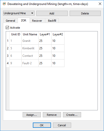
Figure 9.21 “ZOR“ definition for an underground mine
The “ZOR” tab is used to add the ZOR file created using the “Zone of Relaxation for Caving” dialog box to the model. The “ZOR” tab has the following options:
- Activate:
This checkbox is a switch to activate the ZOR for the selected underground mine in the model.
- Assign:
This button opens the “Open Time-Varied Conductivity File” dialog box, which is used to select the desired ZOR file.
- Remove:
Removes the ZOR from the underground-mine definition.
- Create:
Opens the “Create Zone of Relaxation for Cave Zone” dialog box.
On the “ZOR” tab, locate the “Assign…” button at the bottom of the dialog box. Click the “Assign…” button and, using the “Open Time-Varied Conductivity File” dialog box, browse to the previously created ZOR file, select it, and click “Open.”
If the ZOR factors need to be altered, they can be updated using the “ZOR” tab (see Figure 9.21). After all changes to the ZOR factors have been made, check the box next to “Activate” to activate the ZOR in the model.
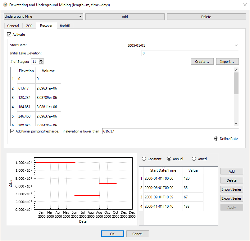
Figure 9.22 “Recover“ tab parameters
Using the “Recover” menu, the user can define groundwater recovery and inflow into the underground workings after the end of mining. The “Recover” tab has the following options:
- Activate:
This checkbox is a switch to activate groundwater recovery for the selected underground mine in the model.
- Start Date:
Defines the start of groundwater recovery, which should be after the end of mining.
- # of Stages:
The number of stages to use to calculate groundwater inflow into the underground workings.
- Create:
Function used to calculate the elevation and volume of each stage. This function is described in further detail below.
- Import:
Function that can be used to import a file containing the stage elevation and volume relationship for groundwater recovery.
- Additional pumping/recharge; if elevation is lower than:
These options allow the user to define an elevation below which additional pumping or recharge is active.
- Define Rate:
This button opens a time-series window that is used to define the rate of additional pumping or recharge for groundwater elevations below the specified level.
On the “Recover” tab, define the “Start Date” of groundwater
recovery and inflow into the underground workings. Next, specify the
“Initial Lake Elevation” if the value MINEDW has automatically
assigned is not desired. The default value is based on the lowest mined
elevation. In the box next to “# of Stages,” enter the number of
stages to use to calculate groundwater recovery in the underground
workings. Note that if importing a file containing the stage elevation
and volume recovery information, the “# of Stages” will be
auto-populated. Next, click on “Create” to open the “Create
Underground Recover Stage” dialog box shown in
fig-underground-recover-tab. This function is used to
calculate the stage elevation and volume information for groundwater
recovery using a 3-D .DXF file and the “# of Stages” input by the
user.
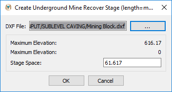
Figure 9.23 The “Create Underground Mine Recover Stage“ dialog box
- DXF File:
Input for the file path and file name of the 3-D .DXF file to use to calculate the stage elevation and volume information for groundwater recovery.
- Maximum Elevation:
The maximum elevation of the underground workings.
- Minimum Elevation:
The minimum elevation of the underground workings.
- Stage Space:
The space of each stage, which is calculated by MINEDW based on the input 3˗D .DXF file and number of stages. This value can be modified by the user if necessary.
After selecting the appropriate .DXF file and verifying the MINEDW calculated information for the stages, click “OK” to close the window. The information for “Elevation” and “Volume” in the “Dewatering and Underground Mining” dialog box is automatically updated. If there is any additional pumping or recharge to be defined, check the “Additional pumping/recharge” box and enter the elevation below which additional pumping or recharge is active in the box to the right. Next, click the checkbox next to “Define Rate” to open the time-series window where pumping or recharge rates are defined. shows the “Recover” tab with the necessary input.
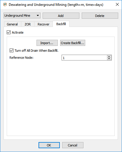
Figure 9.24 The “Backfill“ tab of the “Dewatering and Underground Mining“ dialog box
The “Backfill” tab in the “Dewatering and Underground Mining” dialog box is used to specify backfilling operations of an underground mine. The “Backfill” tab is shown above in Figure 9.24, and the inputs are discussed below.
- Import:
Import will allow the user to import a file describing the backfilling of underground workings.
- Create Backfill:
This will open the “Create Zone of Relaxation for Cave Zone” dialog box, which will allow the user to create a file describing the backfill of the underground workings. The same procedures as described in Open-Pit Backfilling should be followed.
- Turn Off All Drain When Backfill:
This option will turn off all drain nodes that were used to simulate the dewatering of the underground workings. In order for this function to work, the appropriate drain node groups must be added to the “Drain Group Used” window on the “General” tab (see Figure 9.20).
- Reference Node:
The node that is used for a reference elevation.
| Was this helpful? ... | Itasca Software © 2025 | Updated: Sep 23, 2025 |
