9.3. Open Pit Operations
9.3.1. Importing a Mine Plan into MINEDW
After creating the mine plan, select “Open Pit” in the “Mining” drop-down menu to assign the mining file to the model. After the “Open Pit” dialog box opens (see Figure 9.9), click “Add” and browse to the mining plan file; select it and click “Open” in the “Open Mining Plan File” dialog box.
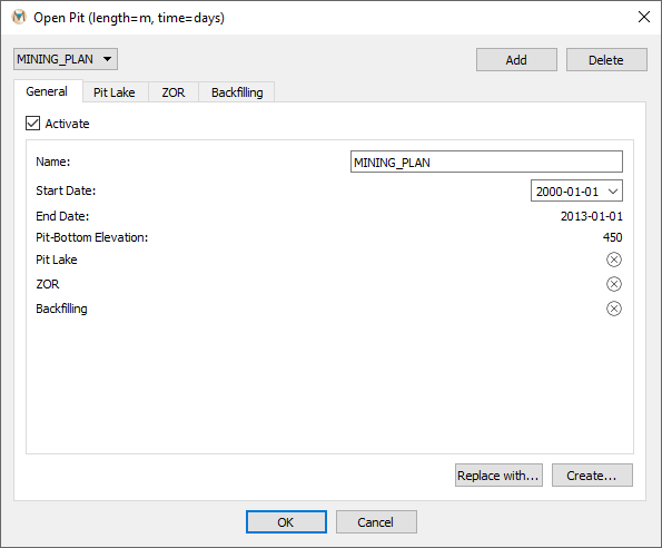
Figure 9.9 The “Open Pit” dialog box
For each pit, there are four different menus: 1) “General,” 2) “Pit Lake,” 3) “ZOR,” and 4) “Backfilling.” Under the general tab, pit-plan information is provided, including the pit name, the start and end dates, and the pit-bottom elevations. In this menu, the user can open a different mining file using the “Replace with” command or create a different mining plan using the “Create” command. Under the other three tabs, a pit lake (Pit Lake), a zone of relaxation (ZOR) (Zone of Relaxation for Pit), and backfilling (Open-Pit Backfilling) can be defined.
Once a mining plan has been imported into MINEDW, the user may visualize the open-pit excavation through time by selecting the “List” tab in the “Control Panel” Pane on the right-hand side of the Main Menu and adding a “3-D Element” plot item. The mesh will be displayed in the View Pane in plan view with geological units. To view pit excavation at a particular time step, enter the time-step number in the box on the time-step slider; otherwise, click on the time-step slider (see Figure 9.10) and move it to the right to view the progressive excavation of the pit through time.

Figure 9.10 Time-step slider
The collapsed mesh showing the open pit with geology will be displayed in the View Pane, as shown in Figure 9.12.
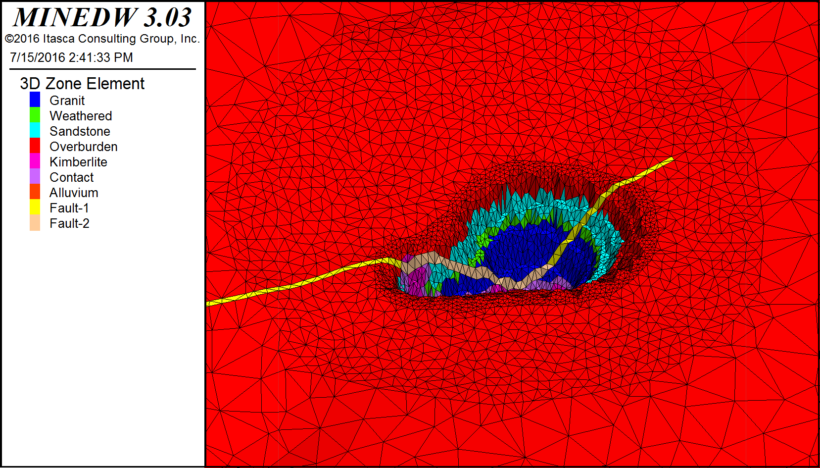
Figure 9.11 The collapsed mesh showing the open pit with geology
The elevation change in the pit area through time can be visualized by selecting the “List” tab in the “Control Panel” Pane on the right-hand side of the Main Menu banner. Expand the “Node” item and double-click “3-D Contour.” The mesh will be displayed on the View Pane in plan view with elevation values. You can deactivate and activate “3-D Element” and “3-D Contour” to switch between the views at desired time steps to visualize the changes in both geology and elevation.
Mining plans for any model simulation can be activated and deactivated by unchecking the “Activate” checkbox. Click “OK” to save the changes and exit the “Open Pit” dialog box.
9.3.2. Pit Lake
When mine operations cease, a pit lake can form if the pit bottom is below the pre-mining water table. To simulate the pit-lake formation in MINEDW, select “Open Pit” from the “Mining” drop-down menu. In the “Open Pit” dialog box (see Figure 9.9), select the pit plan that a pit lake forms under, and then select the “Pit Lake” tab and check the box next to “Activate.” To define a pit-lake simulation, enter a date in the “Start Date” box for the start of the pit-lake formation, an “Initial Lake Elevation,” “Evaporation” rate (if any), and the “# of Stages” in the lake. These options are described in more detail below.
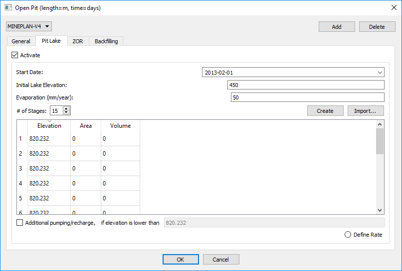
Figure 9.12 The “Pit Lake” tab
The following are options are available in the “Pit Lake” tab:
- Start Date:
Date of when pit-lake infilling will begin. This date must be after mining has ended and equal to or later than the backfilling date if backfilling is applied.
- Initial Lake Elevation:
This value must be equal to or greater than the minimum pit elevation or the pit bottom after backfilling operations. In the case of a sump or area of the pit that already holds water at the start of pit-lake formation, you would enter an “Initial Lake Elevation” greater than the pit bottom.
- Evaporation:
Evaporation rate of the pit lake (millimeters per year [mm/yr] or ft/yr).
- # of Stages:
Number of stages to be used in the simulation. The user must specify the “Elevation” of each stage in the dialog box below the input for the number of stages. MINEDW will calculate the “Area” and “Volume” of the stages.
- Create:
The “Create” function will automatically calculate the area and volume of each stage based on the “# of Stages” the user selects.
- Import:
Using the “Import” function, the user can import a pit-lake file.
- Additional Pump/Recharge:
Switch for additional sources of discharge (-) or recharge (+) (excluding groundwater seepage) when the elevation is lower than a user-specified elevation. When the pit-lake recharge option is activated, click the “Define Rate” button and a new menu (see Figure 9.13) will appear. In this menu, the user can define any additional recharge and pumping to/from a pit lake based on time-series data.
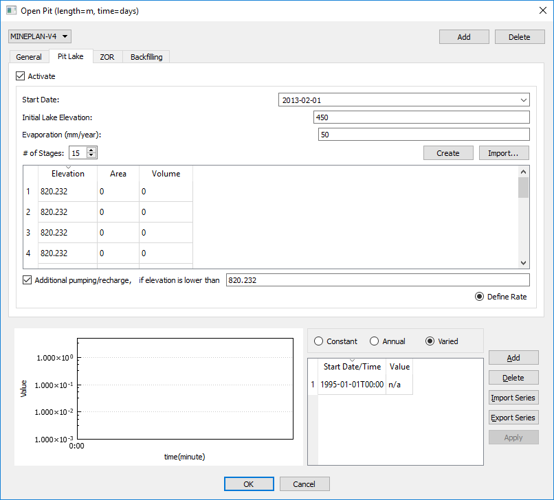
Figure 9.13 Pumping/recharge menu for a pit lake
9.3.3. Zone of Relaxation for Pit
In MINEDW, a ZOR can be created around excavations, backfilling operations, longwall coal mining, room-and-pillar coal mining, freeze-thaw conditions, or other scenarios in which hydraulic conductivity may change during the simulation period.
To create a ZOR for an open pit, select “Open Pit” from the “Mining” drop-down menu. Select the open-pit plan from the drop-down box on the upper left-hand corner of the dialog box and then select the “ZOR” tab (see Figure 9.14).
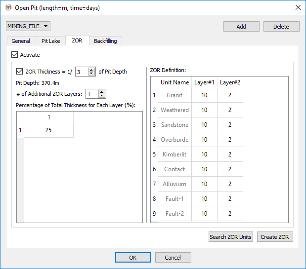
Figure 9.14 The “Open Pit” dialog box with “ZOR” active
MINEDW offers two options for specifying the thickness and shape of the ZOR: as a ratio of the pit depth or by user-defined thicknesses.
Using the first option, the user can further subdivide the ZOR into layers that are also defined using a thickness that is calculated as a ratio of the pit depth. This results in a ZOR that has a minimum thickness at the perimeter of the pit and thickens toward the center of the pit (see Figure 9.15). Layering within the ZOR is defined in percentages of the total ZOR. The sum of user-defined percentages must be less than or equal to 100. In either case, MINEDW will add a layer such that the “ZOR Definition” dialog box will always contain n + 1 ZOR layers (where n is the number defined by the user) (see Figure 9.16). The input file created by MINEDW will always contain n + 1 layers, but the layer added by MINEDW will only be used if the user-defined percentages are less than 100. For example, in a 120-m deep pit with a ZOR thickness equal to ¼ of the pit depth, the ZOR will have a maximum thickness of 30 m. The ZOR can then be divided into two equal layers by entering “2” in the box next to “# of Additional ZOR Layers” and then entering “50%” for both layers. When “Search Zone” is clicked, MINEDW adds an additional layer for a total of three ZOR layers, as displayed in Figure 9.16. The ZOR layers that are used in the simulation are “Layer#1” and “Layer#2.” The layer added by MINEDW, “Layer#3,” is not used. Alternatively, the ZOR could have been created by creating one ZOR layer, entering “50%” for the layer, and then clicking “Search Zone.” In this scenario, the layer created by MINEDW is used and accounts for the remaining 50% of the ZOR (Figure 9.16). Also, it is important to remember that, when MINEDW searches for geological units within the ZOR, it displays all the units for each layer even though the unit may not form part of the ZOR. For example, if the model contains a surficial unit such as alluvium that does not form part of the ZOR, it will be shown in the ZOR dialog window but can be excluded by using a factor of 1 for the hydraulic conductivity multiplier.
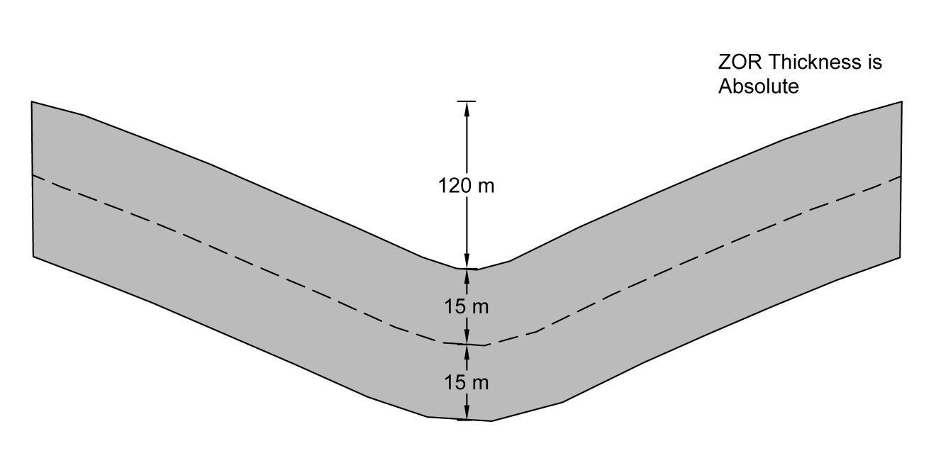
Figure 9.15 Defining the ZOR. A) Default layer is inactive, B) Default layer is active
Using option two, in which the user defines the absolute thickness, the user specifies the number of layers in the ZOR and the thickness (m or ft) of each layer. The sum of these layers will be the ZOR thickness no matter the pit depth, as shown in Figure 9.17.
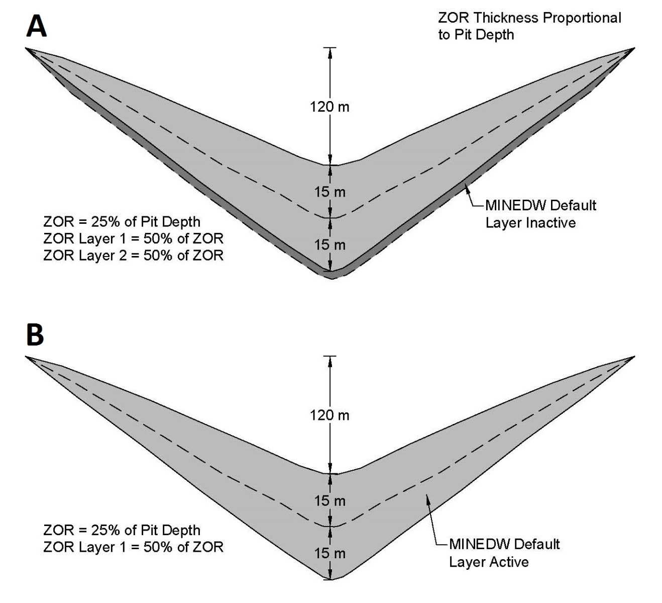
Figure 9.16 Defining the ZOR thickness using absolute thickness layers.
To create a ZOR using option one, click the “ZOR thickness = 1/ of Pit Depth” checkbox to activate the ZOR thickness proportionality option and then choose an appropriate ratio. Next, define the number of layers to use in the ZOR using the toggle buttons next to the “# of Additional ZOR Layers” box or by typing in a number. After that, specify the thickness as a percentage for each ZOR layer, keeping in mind that the cumulative sum of percentages must not exceed 100. MINEDW will provide the user a warning if the cumulative sum is greater than 100%. Layers are ordered from top down, where the top layer forms around the pit surface. Once layer percentages are defined, click the “Search ZOR Units” button and MINEDW finds the geological zones that lie within the defined ZOR. The “ZOR Definition” box, at the right (see Figure 9.14), will contain the results.
To create a ZOR using option two, define the number of layers to use and the thickness of each layer, then click “Search ZOR Units.”
For either method, factors of the original hydraulic conductivity values are entered in the columns labeled “Layer#1,” “Layer#2,” etc. After finishing, click “Create ZOR” to create the ZOR for the open pit and then check the box next to “Activate” at the top left of the “Open Pit” dialog box. Click “OK” to save the changes and close the “Open Pit” dialog box.
Once a ZOR has been created, it can be visualized by selecting the “List” tab in the “Control Panel” Pane on the right-hand side of the Main Menu banner. Expand the “Element” item and double-click “Time Varied Conductivity” (see Figure 9.17).
If the mining plan is modified or replaced with a different mining plan, the ZOR will need to be recreated.
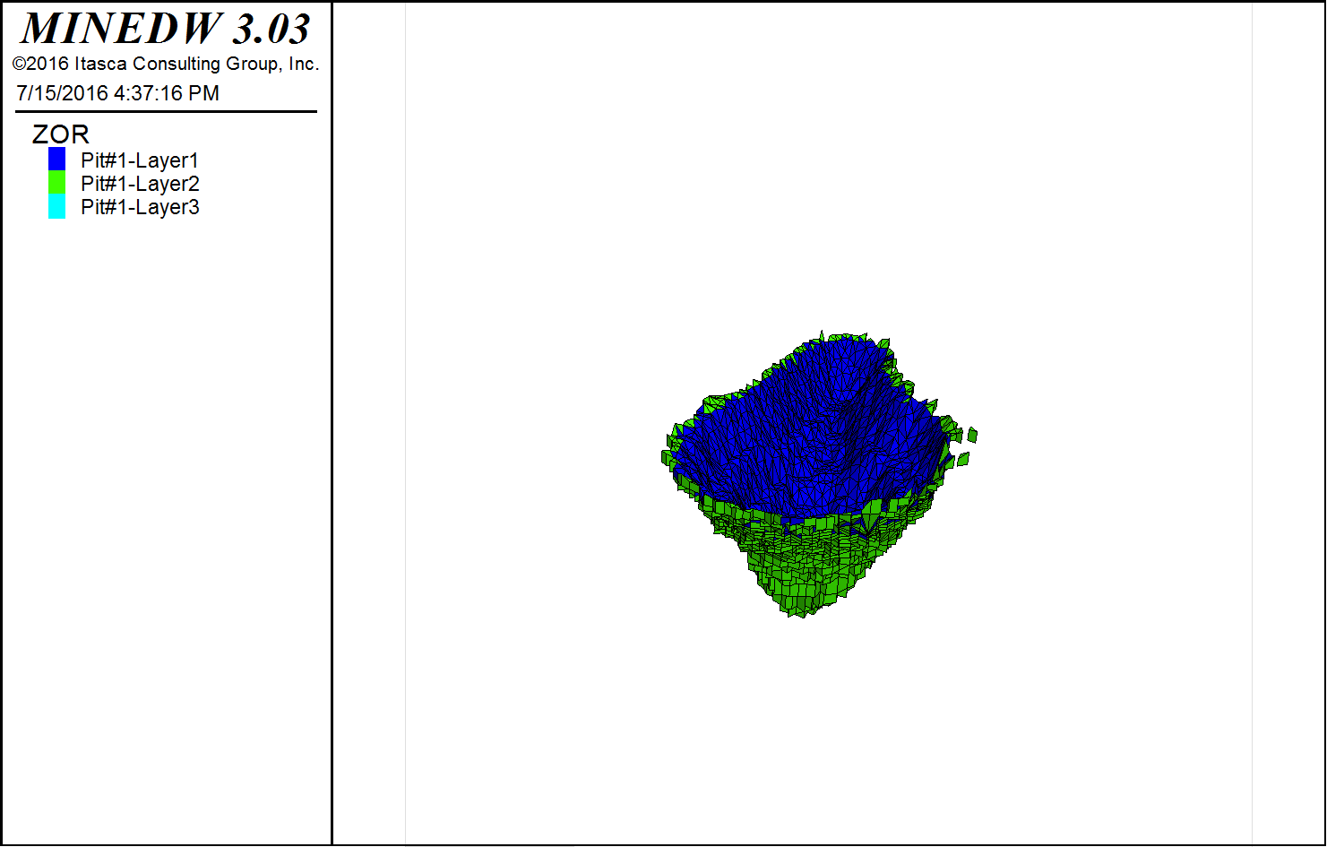
Figure 9.17 ZOR in the model
9.3.4. Open-Pit Backfilling
MINEDW can simulate open-pit backfilling. Backfilling may be used in some mining applications to prevent the formation of a pit lake or to dispose of tailings after mining has ceased. To use this option, select “Open Pit” from the “Mining” drop-down menu. Select the desired pit plan on the left and then click the “Backfilling” tab (see Figure 9.18). Check the “Activate” box and define the “Implement Date” for backfilling. The “Implement Date” of backfilling must be before or the same time as the “Start Date” of pit-lake formation. MINEDW does not support the backfilling of an existing pit lake and automatically adjusts the “Start Date” or “Implement Date” for pit-lake or backfilling operations to prevent backfilling of a pit lake. Backfilling operations are simulated in one time step rather than progressive backfilling over multiple time steps. The backfill elevation can be defined as constant by checking the “Constant Elevation” option and entering a value. Otherwise, if more detailed information is available for the backfill, “Varied” can be checked and the file containing elevation information, in .DAT file format, can be selected in the “Open Data File” dialog box that opens. In the “Grid” dialog box, choose the interpolation method and enter the appropriate parameters. The surface for the backfill is then created. Finally, the hydraulic parameters for the backfill can be selected from the drop-down list (see Figure 9.18). The entire backfilled zone will have the same hydraulic properties and cannot be subdivided. When the “Backfilling” parameters are completely defined, click “OK” in the “Open Pit” dialog box to ensure that the changes are saved.
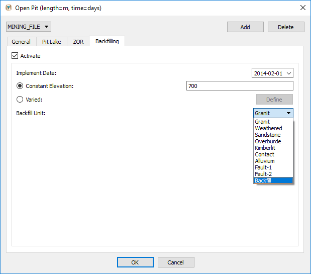
Figure 9.18 The “Backfilling” tab available in the “Open Pit” dialog box
| Was this helpful? ... | Itasca Software © 2025 | Updated: Sep 23, 2025 |
