9.2. Creating a Mining Plan
MINEDW provides the user with two options for entering the mine-plan information, which is used to create the mining-plan file used to simulate progressive excavation of an open pit. The first option is to provide XYZ data of the open pit over time in .DAT files (see below). The second option is to provide XYZ data of the pit at the end of mining (ultimate pit) and pit-bottom elevations through time (Creating a Mining Plan from Final-Pit Topography).
If the XYZ data for pit topography is provided in 3-D .DXF files, they will need to be converted into .DAT file format before they are used to create a mining plan. The Rhino “Drop” function can be used to achieve this or any other program that is capable of manipulating .DXF files. Alternatively, MINEDW provides a function that can be used to convert .DXF files to .DAT file format (Converting .DXF to .DAT files).
To create a mining plan:
From the Main Menu banner, click “Mining”
Select “Create Mining Plan”
The “Create Mining Plan” dialog box appears
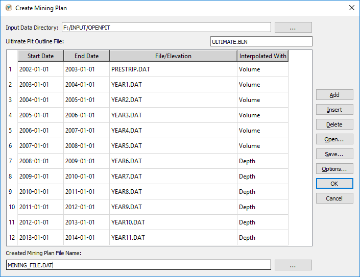
Figure 9.4 The “Create Mining Plan“ dialog box
In this menu, mining plans can be created using the following options:
- Interpolated With:
Select “Depth” or “Volume” methods for temporal interpolation.
- Input Data Directory:
The file path to the location where input files are located must be entered here. Two options are available: manual entry, or by clicking the “…” button, which opens the “Select Directory” dialog box. The “Select Directory” dialog box can be used to navigate to where the input files reside.
- Start Date:
Define the start date of the mining stage.
- End Date:
Define the end date of the mining stage. Periods of no excavation between mining stages can be created simply by ensuring that the start date of the next mining stage does not correspond with the end date of the previous stage. The mining periods for each of the stages, however, cannot overlap.
- Ultimate-Pit Outline File:
Enter pit boundary file name. This file is required to be in a .BLN format.
- Add:
Add additional records to be used in the mining plan.
- Insert:
Insert additional records to be used in the mining plan.
- Delete:
Delete records used in the mining plan.
- Open:
Open a mining-schedule file that contains a list of records to be used in a mining plan.
- Save:
Save a mine plan file. This will save the records of the mining plan to a file that can be imported again with the “Open” option.
- Options:
Menu defining mining-plan spatial-interpolation options. MINEDW uses inverse distance weighting or kriging interpolation methods to create the progressive excavation of the open pit from data files that are provided by the user. The interpolation methods can be changed in the options menu of the “Create Mining Plan” menu. The options menu is displayed in Figure 9.5.
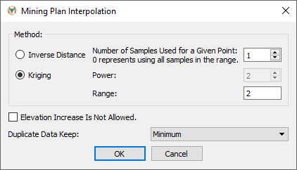
Figure 9.5 The “Mining Plan Interpolation“ dialog box
This menu has the following options:
- Inverse Distance:
Option to use the inverse-distance method for interpolation.
- Kriging:
Option to use the kriging method for interpolation.
- Number of Points to Search:
Data points to use in the kriging or inverse-distance method.
- Power:
Power used in the inverse-distance method.
- Range:
Range used in the kriging method.
- Elevation Increase Is Not Allowed:
Option that does not allow elevation increases in the interpolation method.
- Duplicate Data Keep:
Option to determine which elevation is valid if two elevations exist at one point in one .DAT file. The user can either keep the minimum elevation, maximum elevation, or an average of the elevations.
9.2.1. Converting .DXF to .DAT files
Any .DXF file that will be used to create a mine plan needs to be converted to an XYZ data file (.DAT):
On the “List” tab, double-click “File Data”
Double-click “DXF”
The “Attributes” tab appears
Select the “+” next to the “File” attribute as shown in the green box in Figure 9.6
The “Select DXF data file” dialog box opens
Navigate to the location of the desired .DXF file
Select it and click “Open”
Select the icon next to “To Data File” to save the information as a .DAT file
Repeat the same procedure for all mining
.DXFfiles that are to be used in the mine plan
For .DXF files that have multiple layers, the user may choose the layers that will be used for the mine plan by activating or deactivating the layers using the “Layers” attribute.
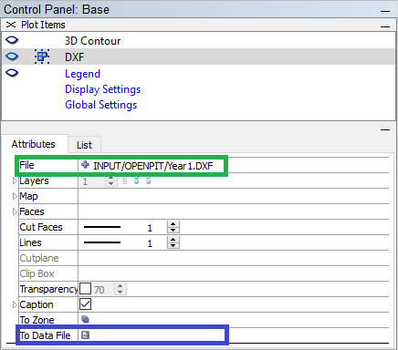
Figure 9.6 Reading a .DXF file and saving as a data file
For any pit plan that is created in MINEDW, a pit outline is needed (e.g., the ultimate-pit boundary) to define the nodes that will be used for interpolation. This boundary needs to be defined using a .BLN file format and is always the first record in the mine plan file. This file defines the perimeter of the pit and does not contain elevation information because all elevations are assumed to be the top of the mesh.
Note: All of the .DAT files that are used to create the mining plan file must be located in the same directory.
9.2.2. Creating a Mining Plan from Pit Topography files
The following is a guide to creating a mining plan and schedule based on XYZ data of pit topography stored in .DAT files.
To create a mining plan from pit topography files:
From the Main Menu, click “Mining” and then select “Create Mining Plan”
Enter the file path to pit topography files (.DAT format) in the “Input Data Directory” box
Enter the ultimate-pit boundary file name in the “Ultimate Pit Outline File” box
Click “Add” to add a record for each pit topography file
For each file, enter: - File name - Corresponding start and end dates - Choose “Depth” or “Volume” under “Interpolated With”
Enter a name for the new mining plan file in the “Created Mining Plan File Name” box
Alternatively, click the button next to the data entry box to select a different directory and enter a file name (see Figure 9.7)
Alternatively, the data detailed in the above steps can be imported from a “Mine Plan File.” If a “Mine Plan File” is available, click “Open…” in the “Create Mining Plan” dialog box and navigate to the location of the “Mine Plan File.” Select it and then click “Open.” The directory path, mining start date, ultimate-pit boundary file name, pit-geometry files, and associated dates will be populated. The default for “Interpolated With” is “Depth.” If the “Volume” method is desired, then be sure to select it for the appropriate mining stages. Finally, enter a name for the new mining plan file in the “Created Mining Plan File Name” box or, to select a different directory than the directory where the mining files are located, click the button next to the data entry box and select the desired file location and enter a file name.
Figure 9.7 The “Create Mining Plan“ dialog box with pit plan
When the appropriate data have been entered in the “Create Mining Plan” dialog box, click “OK” and MINEDW creates the mining file. The file will need to be imported into the model using the “Open Pit…” menu, which is discussed in more detail in Importing a Mine Plan into MINEDW.
9.2.3. Creating a Mining Plan from Final-Pit Topography
To create a mining plan from final-pit topography:
From the Main Menu banner, click “Mining” and select “Create Mining Plan”
Enter the ultimate-pit boundary file name in the “Ultimate Pit Outline File” box
Click “Add” to add a record
Enter the .DAT file name containing the ultimate-pit topography
Enter appropriate start and end dates and file name under “Date” and “File” for the ultimate pit
Click “Insert” to add records above the previously created record
For these newly created records, enter: - Pit-bottom elevation in the “File/Elevation” column - Start date in the “Start Date” column - End date in the “End Date” column (see Figure 9.8).

Figure 9.8 The “Create Mining Plan“ dialog box with pit plan
Once the appropriate data have been entered in the “Create Mining Plan” dialog box, click “OK” to create the mining plan file.
| Was this helpful? ... | Itasca Software © 2025 | Updated: Sep 23, 2025 |
