7.3. Zone Properties – Hydraulic Parameters
This section describes zone properties (hydraulic parameters) assigned to the model. The term “zone” refers to the aquifer material composing each element; each element has a zone type. Zone definitions change only when moving a geologic boundary or defining a new geologic material. Zone definitions include hydraulic conductivity, specific storage, specific yield, and principal directions of the hydraulic conductivity field in x, y, and z directions.
The hydraulic parameters that characterize each zone are defined by selecting “Project” and then “Zone Properties” (Figure 7.24).
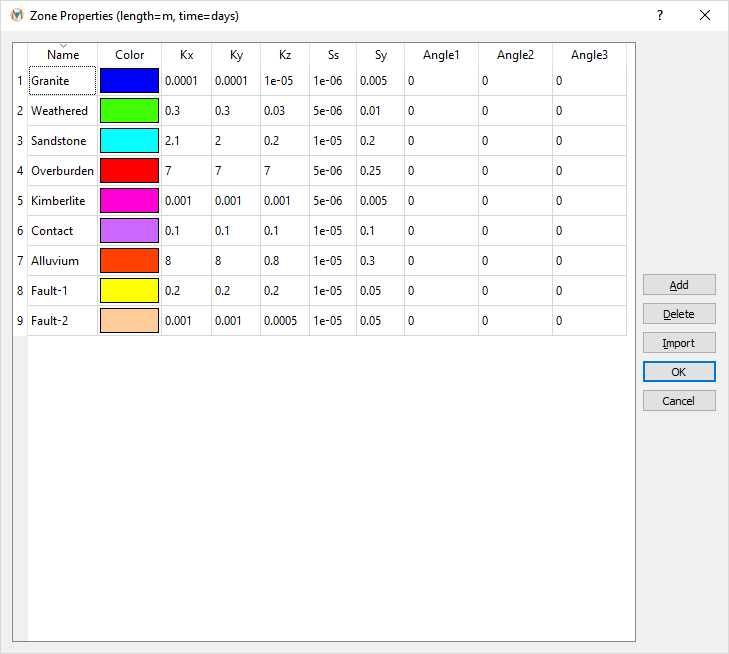
Figure 7.24 The “Zone Properties“ dialog box
The information provided in the “Zone Properties” dialog box is described below.
- Name:
Name of the geologic unit. The name is used in the display and output files.
- Kx:
Hydraulic conductivity in x direction (meters per day [m/day] or feet per day [ft/day]).
- Ky:
Hydraulic conductivity in y direction (m/day or ft/day).
- Kz:
Hydraulic conductivity in z direction (m/day or ft/day).
- Ss:
Specific storage (m-1 or ft-1).
- Sy:
Specific yield (-).
- Angle1 (Φ):
3-D anisotropy, the angle of rotation around the z-axis in degrees.
- Angle2 (θ):
3-D anisotropy, the angle of rotation around the y-axis in degrees.
- Angle3 (ψ):
3-D anisotropy, the angle of rotation around the x-axis in degrees.
The angles (”Angle1,” “Angle2,” and “Angle3”) used to define the hydraulic conductivity tensor are illustrated in Figure 7.25. As described above, the direction of rotation is around the z-axis, y-axis, and finally the x-axis.
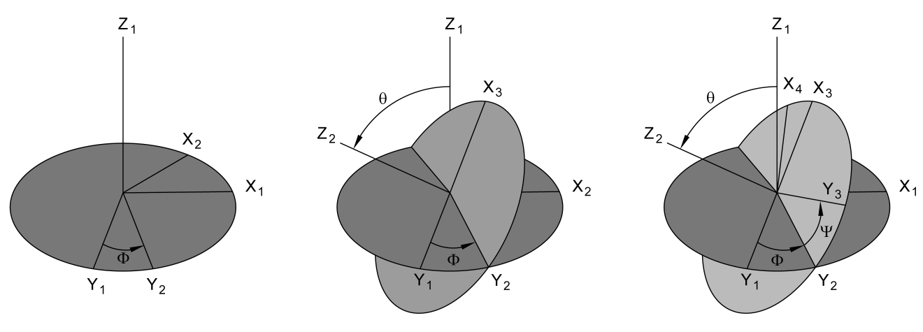
Figure 7.25 A graphical illustration of Angle1 (Φ), Angle2 (θ), and Angle3 (Ψ)
After defining the “Zone Properties,” see the explanation in Nodes and Elements on how to select elements and assign them with the created hydrogeological zones.
7.3.1. Zone Distributions (para.fem)
As described in Nodes and Elements, hydraulic zone properties can be assigned using the “Select” tool and the “Select Geology Zone” dialog box or a 3-D .DXF. Another method is to import a “para.fem” file, which contains the hydraulic zone definition for each element in the model domain. This file consists of three columns of data: 1) the element number, 2) the hydraulic zone number, and 3) the element layer number. This file can be created using another MINEDW model with the same domain or other software.
To import a “para.fem” file and change the distribution of hydraulic parameters of a model, click on “Import Zones from Parameter File” under the “Project” drop-down menu on the Main Menu banner. Using the “Import Zone File” dialog box, navigate to the location of the “para.fem” file, select it, and click “Open.” The new hydraulic zone distribution will be assigned to the model domain.
7.3.2. Zone Properties (kfile.dat)
New parameter values for hydraulic zones can be imported into MINEDW from the “kfile.dat” file, which can be edited by any text editor. To import a new “kfile.dat,” open the “Zone Properties” dialog box (see Figure 7.24). Using the “Import” button, open the “Open Zone Properties File” dialog box. Navigate to the location of the new or updated “kfile.dat,” select it, and click “Open.” The parameter values will be updated in the “Zone Properties” dialog box.
| Was this helpful? ... | Itasca Software © 2025 | Updated: Sep 23, 2025 |
