7.2. Model Geometry
While horizontal geometry is defined in the mesh generator, 3-D layering is defined within the MINEDW GUI using the “Mesh” menu. The following sections describe the functions in the “Mesh” menu.
7.2.1. Generating the Mesh
The finite-element mesh defines the geometry to simulate a groundwater system. The MINEDW finite-element mesh consists of a solid configuration of tetrahedrons. Tetrahedrons are difficult solids to use; therefore, the actual mesh is assembled from prismatic elements that are triangular in plan view. The prisms are oriented spatially with sub-horizontal triangular faces and sub-vertical quadrilateral faces. Three tetrahedrons then are automatically fitted into each prismatic element.
To allow flexibility in the construction of 3-D meshes, the MINEDW program accepts prismatic elements that have edges with a height of zero. A prismatic element with one zero-height edge contains two tetrahedrons and an element with two zero-height edges. These special elements can be used to represent geologic features that taper to a thickness of zero or to add vertical refinement in areas of particular interest. Without these special elements, a vertical zone of fine vertical discretization can be terminated only by carrying it to the edge of the model domain.
Generating a MINEDW mesh involves these steps:
Generate a one-model-layer mesh that incorporates the hydrogeologic features in plan view using Rhinoceros 3D and Grasshopper (as described in Mesh Generator) or another mesh generator.
Add the ground-surface topography to the main model layer.
Add main model layers according to the stratigraphy, geologic information, or other data.
If needed, add additional vertical model discretization using pinch-outs.
7.2.2. Adding Main Model Layers
After importing the mesh generated by Rhinoceros 3D and Grasshopper (Mesh Generator), add main layers by selecting “Define Main Layer” from the “Mesh” drop-down menu on the Main Menu banner. A main layer extends through the entire model domain. When “Main Layer” is selected, the dialog box appears.
To add a new main layer to the model, first select a main layer, then click “Insert.” The new main layer will appear above the selected main layer. The “Method” option will be “Constant,” and the “Value” field will be blank. Select the desired method from the drop-down box in the “Method” field if needed, and then enter the appropriate value in the “Value” field. Click “OK” to add the main layer with the desired elevation or thickness. Note: if the “Average” method is selected, then no value is needed in the “Value” field. The new main layer is placed above the originally selected main layer.
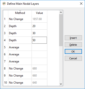
Figure 7.4 The “Define Main Nodal Layers“ dialog box with layer definition
The method of defining the elevation of the main layers in Figure 7.4 includes five options, as shown in Figure 7.5.

Figure 7.5 The “Method“ drop-down box showing the available options
The five options for main layer creation:
No Change: Retains the existing elevation for the selected main layer.
Constant: Assigns a constant-elevation value.
Average: Assigns an average elevation of two layers to the newly created main layer. Not available for top and bottom main layers.
Thickness: Assigns elevation using the defined thickness from the main layer below. Not available when adding the bottom layer.
Depth: Assigns elevation using the defined depth from the main layer above. Not available when defining the top layer.
The following are examples for inserting several main model layers into MINEDW:
Constant: Adding a main layer using the “Constant” method will add a nodal layer at the elevation specified in the “Value” field. A nodal layer (creating two new element layers) can be added anywhere using this method, but care must be taken to ensure that the new layer falls between the nodes of the upper and lower node layers.
Average: To add a main layer with an average thickness (Figure 7.6), select a layer and click “Insert.” MINEDW will insert a nodal layer above the selected layer. Select “Average” from the “Method” drop-down box and click “OK.” MINEDW adds a new nodal layer (as shown within the red box) between the top and bottom nodal layers, forming two element layers. Node elevations for this layer are calculated as the average of the top nodal layer and the bottom nodal layer.
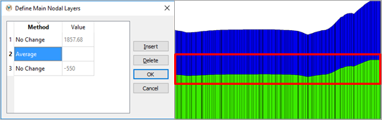
Figure 7.6 Layer definition using the “Average” method
Thickness: The “Thickness” option will create a nodal layer (shown within the red box) that is offset by a user-specified value from the nodal layer immediately below, as seen in Figure 7.7. This creates an element layer with elements of uniform thickness. Figure 7.7 displays a nodal layer that has a constant elevation and an element layer of uniform thickness; however, it is possible to create a nodal layer that does not have a constant elevation but that forms an element layer of uniform thickness. This occurs when the reference nodal layer does not have a constant elevation.
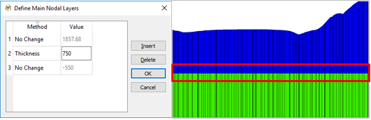
Figure 7.7 Layer definition using the “Thickness” method
- Depth: The “Depth” method is similar to the “Thickness” method,
with the exception that the upper nodal layer (rather than the lower nodal layer) is used as the reference layer to calculate the location of the nodal layer that is being added. In contrast to the nodal layer with uniform elevation, shown in Figure 7.7, the nodal layer in does not have a uniform elevation because the upper nodal layer that was used as the reference to calculate the location of the new nodal layer did not have a uniform elevation.
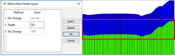
Figure 7.8 Layer definition using the “Depth“ method
7.2.3. Using Topography Data
The following describes how to add topographic information to the first model layer, but the same steps can be repeated to apply topography to any model layer.
To incorporate topography in a model, select the “List” tab in the “Control Panel” Pane on the right-hand side of the MINEDW Main Menu. Expand the “Node” item by double-clicking “Node” or clicking on the small triangle next to “Node.” Next, double-click “3D Contour,” as shown in Figure 7.9. The mesh will be displayed in the View Pane.
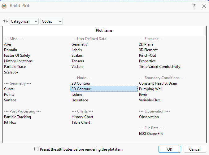
Figure 7.9 The expanded “Node“ plot item group
Click the “Select” tool on the toolbar. From the “Control Panel” Pane on the right-hand side of the MINEDW window, select the “Attributes” tab. Make sure that “Layer 1” is selected and “Elevation” (in the “Color By” drop-down box) is selected, as shown in Figure 7.10.
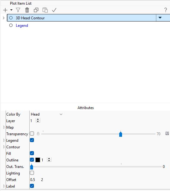
Figure 7.10 The “Control Panel“ Pane showing the “Attributes” tab with “Layer“ set to “1“
In the MINEDW View Pane, use the cursor to click and drag a box around the whole domain to select all of the nodes in Layer 1. Press the [Enter] key to open the dialog box shown in Figure 7.11. Click the button next to “Interpolate From File,” and the “Open Data File” dialog box appears. Select a file with XYZ data (this file is formatted as columns of x, y, and z data) that contains the topographic information that will be added to the model, and click “Open.” The “Grid” dialog box shown in appears. Define the interpolation method (”Inverse Distance” or “Kriging”) and the required parameters, and then click “OK.” MINEDW assigns the topographic information contained in the data file to the top layer of the model using the interpolation method. This method can be used to assign elevation data to all of the nodal layers in the model. To assign elevation data to other nodal layers, simply select the desired layer on the “Attributes” tab of the “3-D Contour” plot item and repeat the steps described above.
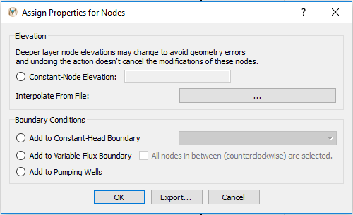
Figure 7.11 The “Assign Properties for Nodes“ dialog box
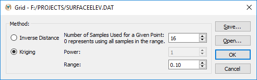
Figure 7.12 The “Grid“ dialog box
To view the ground-surface elevation contours, add an “Isoline” plot item and select “Elevation” as the “Color By” attribute. The counter intervals may be manipulated by using the options under the “Contour” attribute of the “Isoline” plot item. Click on the “Attributes” tab in the “Control Panel” Pane, and then click on the small triangle next to “Contour.” Deselect the “Auto” box next to “Interval” and replace the current value with a different value, then press the [Enter] key, and elevation contours appear. An example of ground-surface elevation contours is shown in Figure 7.13.
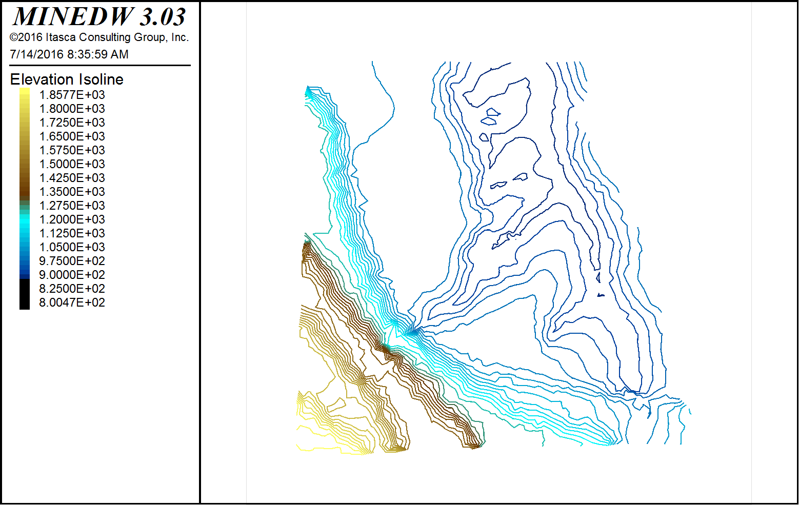
Figure 7.13 The MINEDW main window showing elevation contours
7.2.4. Importing Node Elevations
Node elevations can be assigned to all of the nodes in the model domain by importing a node-elevation file. Node elevations are written to a file called “node.fem” by the MINEDW GUI. This file is a simple text file that can easily be created using another MINEDW model or other software. The file contains five columns of data: 1) node number, 2) x location of node, 3) y location of node, 4) z location (or elevation) of node, and 5) node layer.
To import and assign node elevations for the entire domain, select “Import Elevations From Node File” found under the “Project” drop-down menu on the Main Menu banner. Use the “Import Node File” dialog box that opens to navigate to the location of the node elevation file. Select it and click “Open” to complete the assignment. The default file type for node elevations in MINEDW is the .FEM file type. MINEDW creates three files with the .FEM extension, but only the “node.fem” file can be used to import node elevations.
7.2.5. Defining a Pinch-Out
MINEDW provides the option of adding areas of increased vertical discretization. The enhanced vertical discretization is referred to as a pinch-out because layers terminate in areas where increased vertical discretization is not needed. To define the pinch-out types, select “Mesh” from the Main Menu banner and then select “Define Pinch-Out.” The “Define Pinch-Outs” dialog box appears (Figure 7.14).
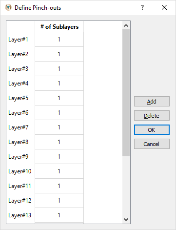
Figure 7.14 The “Define Pinch-Outs“ dialog box
In MINEDW, various pinch-out configurations can be defined and simulated. Each configuration is defined as one type of pinch-out. Based on their modeling needs, the user can define as many pinch-out types as necessary. Each type can contain pinch-outs of as many layers as needed.
Figure 7.15 illustrates the working principle of the pinch-out method.
For example, consider a model with four regional layers (Layer 1 to Layer 4, from top to bottom), each represented by a row of black squares in Figure 7.18. The left column indicates the number of pinch-out layers allowed for each model layer (shown in blue).
For illustration, three different combinations are shown, each defined as a different type in Figure 7.18:
Type 1: Three pinch-outs on model Layer 2 (red lines).
Type 2: Three pinch-outs on model Layer 2 (red lines) and two pinch-outs on model Layer 3 (green line).
Type 3: Two pinch-outs on model Layer 3 (green line).
Only one number of pinch-outs can be defined per model layer. For instance, in Figure 7.18, model Layer 2 cannot have three pinch-outs in one area and two in another. In this example, any area where pinch-outs are added to model Layer 2 will contain exactly three pinch-outs.
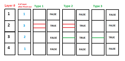
Figure 7.15 Schematic explanation of pinch-outs
To define pinch-outs, click the “Add” button on the right side of the “Define Pinch-Outs” dialog box. Type the number of pinch-outs for each layer in the column labeled “# of Sublayers,” and enable the pinch-out for the related layer by checking the box. Figure 7.16 shows how to define pinch-outs to achieve the schematic shown in Figure 7.18. When the pinch-out types are completely defined, click “OK.”
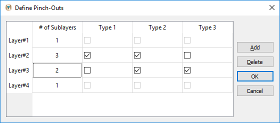
Figure 7.16 The “Define Pinch-Outs“ dialog box
In this example, “Type 1” will have three pinch-outs in Layer 2, while “Type 2” will have the same three pinch-outs in Layer 2 as well as two pinch-outs in Layer 3. “Type 3” pinch-outs will have only two pinch-outs in Layer 3. To assign pinch-outs to an area, select the “List” tab in the “Control Panel” Pane. Expand the “Element” item and double-click “Pinch-Out.” From the main window, click the “Select” tool on the Main Menu banner. Then use the “Select with Polygon” tool to select the area where pinch-outs are to be added. shows an example of the nodes being selected for adding pinch-outs.
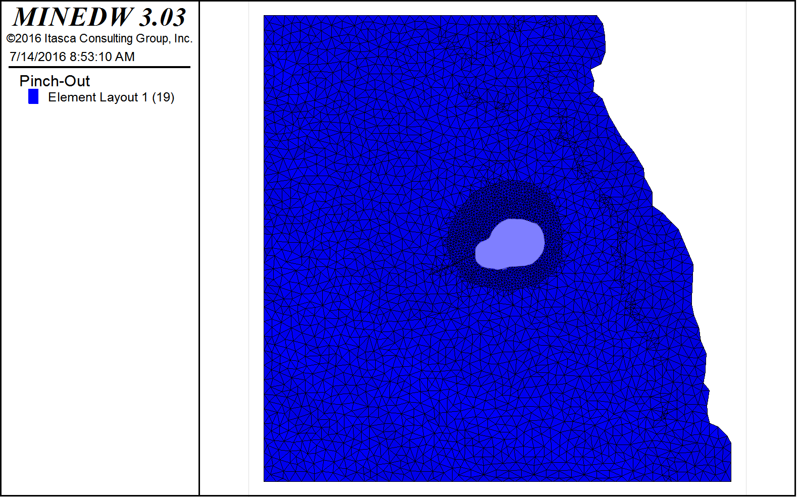
Figure 7.17 The View Pane with the selected nodes for pinch-out Type 1
Press the [Enter] key, and the “Select Pinch-Out Type” dialog box opens (see Figure 7.18). Select the type of pinch-out to add to this location from the drop-down list and click “OK.”
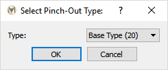
Figure 7.18 The “Select Pinch-Out Type“ dialog box
shows the pinch-outs described in the previous figures in the View Pane.
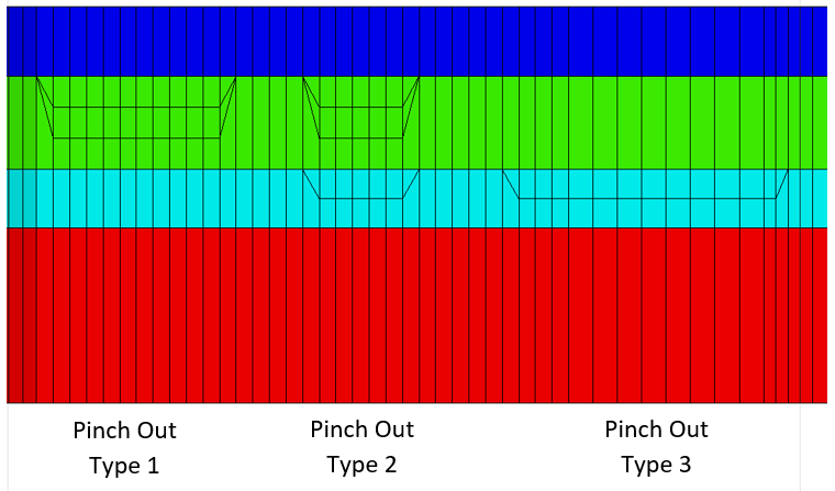
Figure 7.19 Cross-sectional view of the defined pinch-outs
7.2.6. Modifying the Mesh
Using the “Modify Mesh” function in MINEDW, the user can extend the model domain and refine the mesh after it is created or at any time during the model setup. The mesh can be refined in a user-specified location or extended to cover a larger area.
To refine the mesh, click “Modify Mesh” from the “Mesh” drop-down menu found on the Main Menu banner. This will open an “Open BLN File” dialog box (see Figure 7.20). Select a .BLN file that defines an area inside the current model domain to refine and click “Open.”
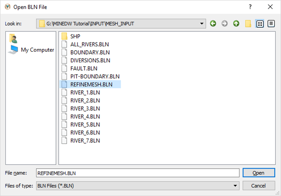
Figure 7.20 The “Open BLN File“ dialog box
The “Refine Mesh” dialog box shown in appears. If the .BLN file defines an area unconnected to the current model mesh, the operation will yield a warning message. Enter the mesh density and click “OK.”
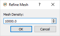
Figure 7.21 The “Refine Mesh“ dialog box
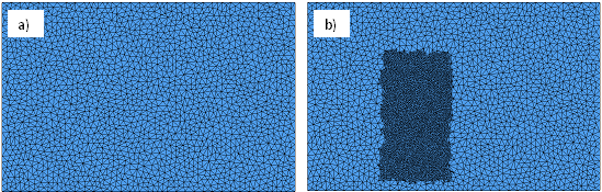
Figure 7.22 The mesh before (a) and after (b) an area of the mesh was refined
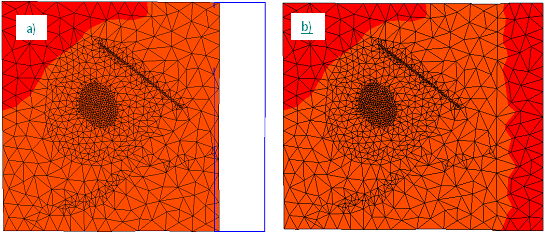
Figure 7.23 The mesh before (a) and after (b) mesh extension
MINEDW can also extend the mesh after it has been created. Click “Modify Mesh” from the “Mesh” drop-down menu found on the Main Menu banner. The area to be extended is defined by a .BLN file created in Surfer™ or in a text editor. When “Modify Mesh” is selected from the “Mesh” drop-down menu, the “Open BLN File” dialog box shown in appears. Select the .BLN file defining the area to be extended. Click “Open.” The “Refine Mesh” dialog box shown in appears. Enter the mesh density and click “OK.” shows the mesh before and after the mesh extension.
| Was this helpful? ... | Itasca Software © 2025 | Updated: Sep 23, 2025 |
