7.1. Project Definition
The first step in creating a new model is defining project properties. This section describes project properties including simulation parameters, units, simulation type, solver types, and file output names.
7.1.1. Project Properties
Define project properties by selecting Project Properties from the Project menu on the Main Menu banner. This opens the Project Properties dialog shown in Figure 7.1 to configure required parameters.
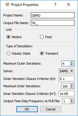
Figure 7.1 Project Properties dialog box
- Project Name
The user-defined name of the project.
- Output File Name
The prefix assigned to all MINEDW-created data files. For example, the model file would be labeled
TR_model.datwhenTR_is the output file name prefix.- Unit
Length units used in the model. MINEDW supports meters and feet.
- Type of Simulation
Select whether the model is steady-state or transient.
Steady-state: Storage changes should be smaller than 1.0 × 10⁻¹⁰ m³/day at simulation end. Only the first time step is used, with subsequent time-step lengths multiplied by 1.2.
Transient: Uses all defined time steps with no multiplication factor.
Storage information is found in the budget and output files (
.BUDand.OUT) created in the simulation directory. Time step configuration is discussed in Time Steps.- Maximum Outer Iterations
Maximum outer iterations (typically an even number less than 10) used to precondition equation matrices before solving. The value depends on solver and model complexity. Start small and increase based on percent residuals in
.BUDor.OUTfiles to optimize solution time.- Solver
Select the solver type for the model simulation. MINEDW provides two solver options:
PCG - Preconditioned Conjugate Gradient
SAMG - Algebraic Multigrid Methods for Systems (Fraunhofer SCAI 2013)
- Outer Iteration Closure Criterion
The head closure criteria for outer iterations. This value depends on the model scale and should generally be less than 1 meter (3 feet). Define the value based on computational time, accuracy requirements, and mass balance considerations.
- Maximum Inner Iterations
Maximum number of inner iterations to solve the matrices of equations. This value is typically greater than 1,000, depending on the inner iteration closure criterion. Inner iterations can often be set to a large value without compromising run time because solvers use only the minimum iterations necessary to meet closure criteria.
- Inner Iteration Closure Criterion
The closure criterion for inner iterations, typically less than 1 × 10⁻¹⁰. Smaller values increase computational accuracy but require longer computation time.
- Output Time Step Frequency to PLB File
The time-step intervals at which MINEDW saves simulated heads to the output file with a
.PLBextension. The default value is 1.
7.1.2. Time Steps
Define time steps using the Time Steps item in the Project menu. The dialog depends on simulation type:
Steady State: Shows the Setup Time Step dialog box (see Figure 7.2)
Transient: Shows the transient Setup Time Step dialog box (see Figure 7.3)
For steady-state models, only Start Date/Time, Maximum # of Time Steps, and Initial Time Step Length need to be defined. The # of Time steps for this simulation parameter is typically the same as Maximum # of Time Steps for steady-state models.
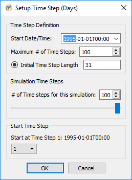
Figure 7.2 Setup Time Step dialog box for steady-state simulations
Transient Simulation Time Step Options
For transient simulations, there are three options for defining time steps:
Constant - Fixed time step intervals
Month - Monthly time steps
Varied - Variable time steps imported from an ASCII file
When Varied is selected, data can be imported from an ASCII file with two columns: time-step number and number of days for each time step. The time steps and corresponding dates are displayed on the right side of the window. The Maximum # of Time Steps setting applies to all simulations within a project.
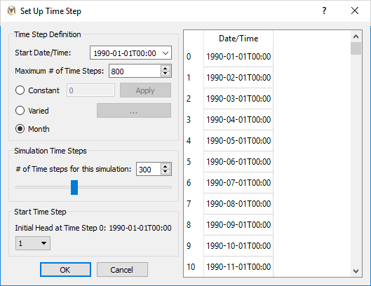
Figure 7.3 Setup Time Step dialog box for transient simulations
Simulation Control
In the simulation time-step section, you can specify the number of time steps to simulate using either the slider or direct entry. This allows you to run either:
Complete simulation - All defined time steps
Abbreviated simulation - A specified subset of time steps
Simulation Restart
Models can be restarted from any specified time step using the
simulation start time drop-down box. The simulated head output file
(.PLB) must be read before selecting the restart time step;
otherwise, only the first time step will be available.
Note
Model simulations should not be restarted during pit-lake filling operations.
For information on reading output files, see Read Results and Export Results as Text File.
| Was this helpful? ... | Itasca Software © 2025 | Updated: Sep 23, 2025 |
