5.2. The Mesh Components
The template contains the following components, which are labeled by number in the template:
Domain: Defines the model domain extent using a single closed polyline curve as input.
Mining Area, Mining, and Fine Area: Outline regions requiring finer mesh discretization using one or more closed polyline curves as input.
Fault: Defines faults in the model domain. The mesh generator ensures nodes follow the fault line and applies user-specified width for accurate geologic representation. Input is a curve representing the fault centerline.
Points: Specifies points that must correspond to mesh nodes, such as pumping wells. Input consists of one or more points.
Polylines: Specifies curves that must correspond to mesh edges, such as rivers or streams, without associated width. Input consists of one or more curves.
Regions: Combines all mesh regions from the “Mesh Regions” group and connects the output to the “MMesh” component’s regions input.
All Faults: Combines all faults from the “Faults with Different Widths” group and connects the output to the “MMesh” component’s faults input.
MMesh: Receives input from regions, faults, lines, and points to generate a mesh. Mesh information appears in the yellow box.
Toggle: Toggles between “True” and “False” values for the “Simplify Lines” parameter. When “True,” “MMesh” simplifies line inputs; when “False,” it preserves original line inputs.
Area Tolerance: Specifies the minimum ratio between an element’s actual area and the maximum area assigned to its mesh region.
The user must import or create each feature in Rhino prior to connecting the features to the Grasshopper workflow. Note that all features must be located in the same 2-D plane. To connect features that exist in the Rhino workbook to the Grasshopper workflow, right-click on the input parameter in the top left corner of the component block and choose “Set One Curve/Point” or “Set Multiple Curves/Points.” Then select the desired feature in Rhino. This process is described in detail for each type of component in the following sections.
For the “Mesh Regions” components, in the purple box in the upper left of the Grasshopper worksheet, all active components must be connected to the “Regions” component. The “Regions” component must then be connected to “MMesh” at the terminal labeled “Regions.”
5.2.1. The “Domain” Component
The Domain component is used to specify the model domain boundary. All parts of the mesh must be contained within the model domain boundary. The input for this component must be a closed polyline curve. The Domain component and its associated menus are shown in Figure 5.2. Note that curves that the user draws in Rhino may be non-uniform rational basis spline (NURBS) curves. NURBS curves cannot be used in the Grasshopper workflow but may be easily converted to polylines using the “Convert” command in the Rhino command line. See the Rhino documentation for more information. To connect a closed curve in the Rhino workbook to the “Domain” component in Grasshopper, right-click on the “Domain” input parameter in the upper left of the component. Select Set One Curve from the menu. Then select the curve that delineates the model domain boundary in the Rhinoceros window.
The user can check that the desired curve was connected to the Domain component by clicking on the Domain component so that it is highlighted in green. In the Rhino workbook, any curve that is assigned to the highlighted component will turn green. Curves may be disconnected from the Domain component by right-clicking on the Domain input parameter and selecting the Clear Values option in the Domain menu, shown in Figure 5.2 b.
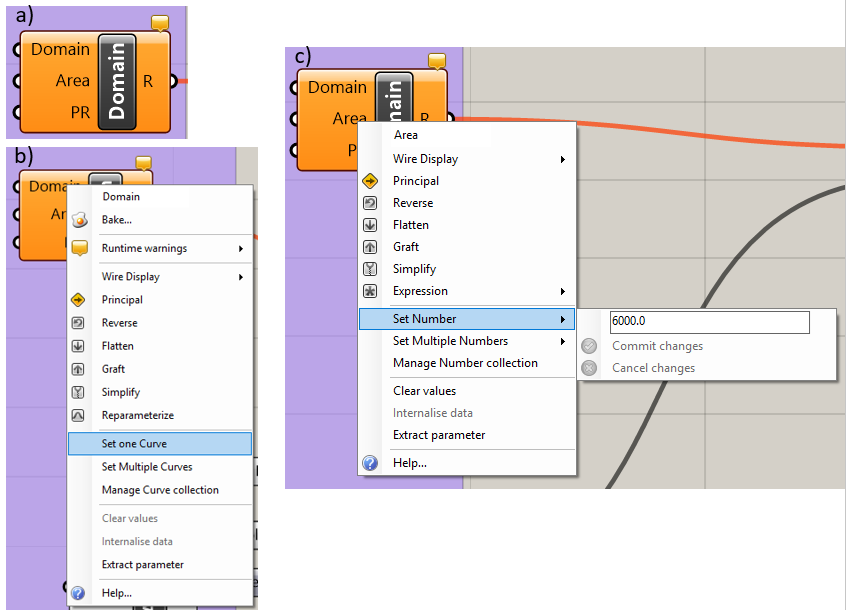
Figure 5.2 The “Domain” component: a) the component, b) the “Domain” input parameter menu, c) the “Area” input parameter menu
The maximum element area is set in two ways depending on whether the “Maximum Area” block and “Area” link in the “Domain” block are connected or not.
If the “Maximum Area” block and “Area” link in the “Domain” block are not connected, the user can right-click on the “Area” input parameter, which brings up the menu shown in Figure 5.2. Click on the “Set Number” menu option and enter the maximum element size desired for the mesh; note that the user will have the ability to add regions of finer discretization.
If the “Maximum Area” block and “Area” link in the “Domain” block are connected, it also is only possible to set the maximum element area by connecting the grey slider to the left of the component, shown in Figure 5.3. The user can either use the slider to determine the value of the maximum area or double-click the grey area and enter the value.
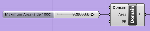
Figure 5.3 The “Maximum Area” slider
It should be noted that if the “Maximum Area” block is connected to the “Area” link of the “Domain” block, the value in the “Maximum Area” block will supersede the value that is entered in the “Area” parameter in the “Domain” block.
Blocks may be connected by clicking on the half circle of the “Maximum Area” block and dragging the mouse to the half circle of the “Area” parameter in the “Domain” block. Blocks maybe disconnected by right-clicking the specific parameter in the “Domain” block (i.e., “Area” in Figure 5.3) and selecting “Disconnect” from the pop-up menu.
5.2.2. The “Mining Area,” “Mining,” and “Fine Area” Components
The “Mining Area,” “Mining,” and “Fine Area” components are intended to allow the user to assign regions of increased mesh density to the area surrounding the mining activities, the location of the mining activities themselves, and any other areas that require it. The regions that the user assigns to any of these three components must be contained within the model domain that the user specified in the “Domain” component. These regions of fine mesh discretization may be located completely inside or completely outside of another fine mesh discretization region; however, they cannot partially overlap.
The “Mining Area,” “Mining,” and “Fine Area” components are used in the same way as the “Domain” component. The user right-clicks on the “Region” input parameter and selects the menu option “Set One Curve” or “Set Multiple Curves” (see Figure 5.2). The user then selects the curve or curves that delineate the region that requires a finer mesh. The user may specify the maximum element area in the region by right-clicking on the “Area” input parameter and selecting “Set Number” from the menu. Alternatively, the user may set the maximum element size by connecting the “Area” input to the “Maximum Area” slider and using the slider to select the desired maximum element size, as shown in Figure 5.3, or enter the value as described in The “Domain” Component.
5.2.3. The “Fault” Component
The Fault component (Figure 5.4 a) is used to create faults that have width. The user must first create or import a curve that delineates the center line of a fault in Rhino. The user right-clicks on the “Line” input parameter and selects the menu option “Select One Curve,” shown in Figure 5.4 b. The user then selects the desired curve in Rhino. The user may also select the “Select Multiple Curves” option and then select all the faults that have the same width. If different widths are desired, the user must use multiple “Fault” components. To disconnect curves, select the “Clear Values” option in the “Line” input parameter menu, shown in Figure 5.4 b.
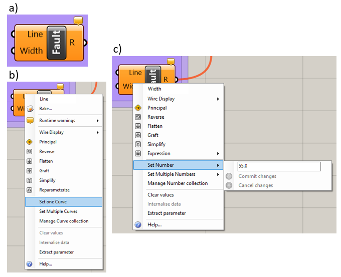
Figure 5.4 The “Fault“ component: a) the component, b) the “Line” input parameter menu, c) the “Width” input parameter menu.
The width of the fault is specified for each “Fault” component by right-clicking on the “Width” input parameter and selecting the menu option “Set Number,” then entering the desired fault width. This is shown in Figure 5.4 c. Alternatively, the user may connect the “Width” slider, shown in Figure 5.5, to the “Width” input parameter and then use the slider to specify the desired fault width. Note that if the slider is connected, the “Set Number” option will be greyed out.
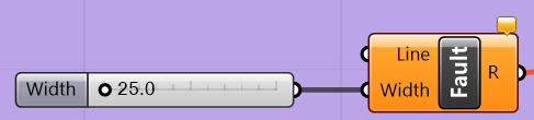
Figure 5.5 The “Fault” component with the width parameter slider
5.2.4. The “Points” Component
The “Points” component (Figure 5.6) allows the user to specify points that will correspond to vertices in the mesh. This is typically used for pumping wells or monitoring wells so that the code’s calculation point will exactly match the location of the point feature. To specify hard points, the user right-clicks on the “Points” component and then selects either “Set One Point” or “Set Multiple Points,” shown in Figure 5.6. The user then selects the desired point or points in the Rhino workbook. The “SelPt” command may be used to select all points in the Rhino workbook. The command line will say “Point object to reference (Type=Point),” where the type is “Coordinate” or “Point.” If the type is “Coordinate,” Grasshopper will save the coordinates of the points at the time it is connected to the Grasshopper workflow. If the point is moved later, Grasshopper will not update its location. When the “Point” type is used, Grasshopper will update the mesh if the point is moved later.
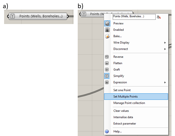
Figure 5.6 The “Points” component: a) the component, b) menu options
5.2.5. The “Polylines” Component
Curves assigned to the “Polylines” component will correspond to mesh edges. This is typically used for rivers or other features that are represented as curves and do not have a width assigned to them. The component is shown in Figure 5.7. To specify a hard curve, right-click on the “Polylines” component and select the “Set One Curve” or “Set Multiple Curves” option, as in Figure 5.7. Select the curve or curves that delineate the desired hard curves.
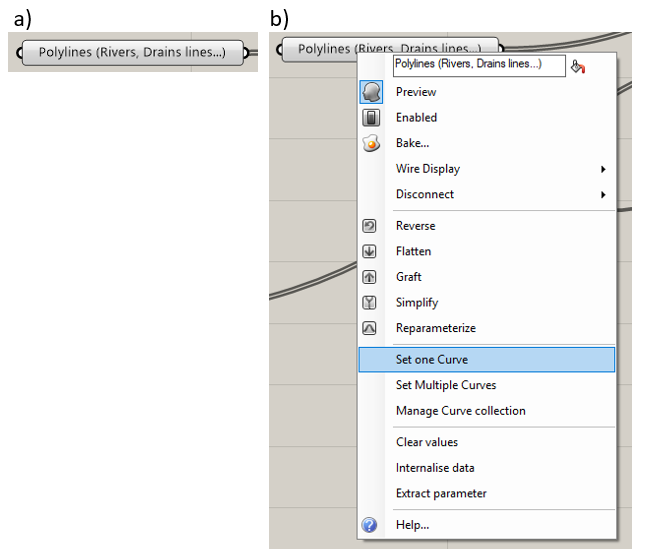
Figure 5.7 The “Polylines” component and menu options
5.2.6. The “Regions” Component
The “Regions” component receives the outputs from each component in the “Mesh Regions” group, merges them together, and outputs the result to the “MMesh” component. The component is shown in Figure 5.8.
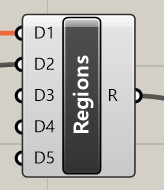
Figure 5.8 The “Regions” component
5.2.7. The “All Faults” Component
The “All Faults” component receives the outputs from each component in the “Faults with Different Widths” group, merges them together, and outputs the result to the “MMesh“ component. The component is shown in Figure 5.9.
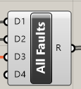
Figure 5.9 The “All Faults” component
5.2.8. The “MMesh” Component
The “MMesh” component, shown in Figure 5.10, receives outputs from the “Regions,” “Points,” “Polylines,” and “Faults” components discussed above. In addition, “MMesh” has an “Area Tolerance“ input parameter, which is the ratio of the smallest permissible area to the corresponding maximum area constraint. There is also a “Simplify Lines” input parameter, which receives a Boolean value from the “Toggle” component. If the value is “True,” all polyline inputs will be simplified, meaning the number of control points will be reduced and redistributed. This is recommended if there is a small angle between curve features. Both the “Area Tolerance” and “Toggle” components are discussed in further detail in the following sections.
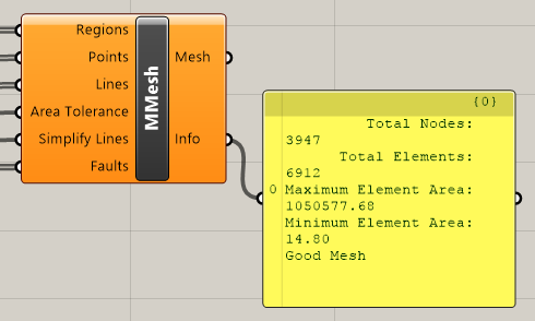
Figure 5.10 The “MMesh” component
5.2.9. The “Toggle” Component
The user assigns either a “True” or a “False” value to the “Toggle” component. In the Grasshopper workflow shown in Figure 5.1, the toggle output is connected to the “Simplify Lines” input parameter in the “MMesh” component. Here, the “Toggle” component allows the user to choose whether or not the “MMesh” component simplifies any line inputs or not; “True” means that lines are simplified, and “False” means that lines are not simplified.
5.2.10. The “Area Tolerance” Component
The “Area Tolerance” component specifies the minimum value of the ratio between an element’s area and the maximum area specified for the region of the mesh that the element belongs to. The “MMesh” routine attempts to create elements that are as close as possible to the maximum element area specified by the user. If the “MMesh” routine is not able to create elements that are large enough to meet the area tolerance criteria, it will disregard hard points so that it can. Therefore, if a curve has too many control points in one section, or if there is a cluster of wells too close together to allow for element sizes to meet the area tolerance criteria, the “MMesh” routine may disregard points that the user specified to match with mesh nodes.
| Was this helpful? ... | Itasca Software © 2025 | Updated: Sep 23, 2025 |
