6.1. Selecting Elements
MINEDW provides several tools for selecting nodes and elements. Selection is essential when performing these tasks:
Assigning and editing element properties (e.g., hydraulic conductivity, storage zones, recharge zones, evaporation zones).
Assigning and editing node-related boundary conditions (e.g., constant heads, pumping wells, variable-flux boundaries).
Moving nodes within the finite-element mesh.
Adding pinch-outs for improved vertical discretization.
Refining and extending the mesh.
6.1.1. Selecting Elements in 2-D
When an element-based plot is displayed, you can select elements using these methods:
Click Selection: Use the Select tool to click individual elements in the View Pane. - Right-click to deselect an element. - Press Esc to clear all selections.
Rectangle Selection: Click the Select tool, then click and drag to define a rectangle. - Right-click and drag a rectangle around selected elements to deselect them.
Polygon Selection: Click the Select tool, then click the Select with Polygon tool (see Mouse Tools). - Draw a polygon around the desired area and press Enter to close it.
After selecting elements, press Enter to open one of these dialog boxes:
These dialogs edit recharge zones, evaporation zones, or geological zones.
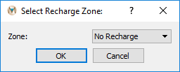
Figure 6.1 Select Recharge Zone dialog box
Recharge Zones To edit recharge zones: 1. Use a 2-D Plane plot item. 2. Change Color By to Recharge. 3. Select elements, then press Enter. 4. In the Select Recharge Zone dialog, assign a zone from the drop-down list.
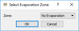
Figure 6.2 Select Evaporation Zone dialog box
Evaporation Zones The process is similar to recharge zones: 1. Change Color By to Evaporation in a 2-D Plane plot. 2. Select elements, press Enter, and assign a zone from the dialog. For details, see Boundary Conditions.
Geological Zones Use a 2-D Element or 3-D Element plot item to assign geological properties. - Select elements, press Enter, and the Select Geological Zone dialog opens (Select Geological Zone dialog box). - To apply changes across multiple layers, specify the target layer in the attribute panel (Select Geological Zone dialog box with multiple-layer option).
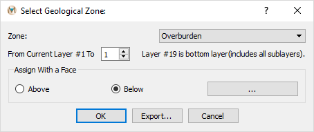
Figure 6.3 Select Geological Zone dialog box

Figure 6.4 Select Geological Zone dialog box with multiple-layer option
Exporting Selections Export selected element numbers using the Export function in the Select Geological Zone dialog. The output file lists selected element IDs.
6.1.2. Selecting Elements in 3-D
Elements and zone properties can also be assigned using a 3-D .DXF file.
Add a DXF plot item to the View Pane:
Select List → File Data → DXF.
In the Attributes tab, expand File and choose the DXF file.
If the DXF contains multiple units:
Open the Layers dialog (Attributes dialog box).
Enable only the desired unit before assignment.
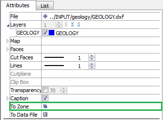
Figure 6.5 Attributes dialog box
Assign zones:
Click the symbol next to To Zone to open the DXF to Zone dialog (DXF to Zone dialog box).
Select the desired zone from the drop-down.
Choose Volume (for 3-D geologic units) or Face (for structures like faults).
Selection modes:
Whole → selects only elements fully inside the DXF object.
Center → selects elements if their centers are inside the DXF object.
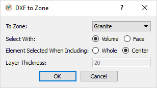
Figure 6.6 DXF to Zone dialog box
6.1.3. Exiting Selection Mode
To exit Select mode, click the View Mode button.
To deselect all elements, press Esc.
| Was this helpful? ... | Itasca Software © 2025 | Updated: Sep 23, 2025 |
