Punch Indentation
Problem Statement
The project file for this example may be viewed/run in FLAC2D.[1] The main data file used is shown at the end of this example.
A rigid punch is driven at a constant velocity into a cohesive, frictionless material. When run in large-strain calculation mode, a “bad geometry” error occurs after driving the punch ~1.9 m into the material (approximately 9400 steps) - see Figure 1. Enabling remeshing logic will allow the punch to be driven almost entirely through the material. The mesh is automatically re-created when a “bad geometry” condition is encountered.
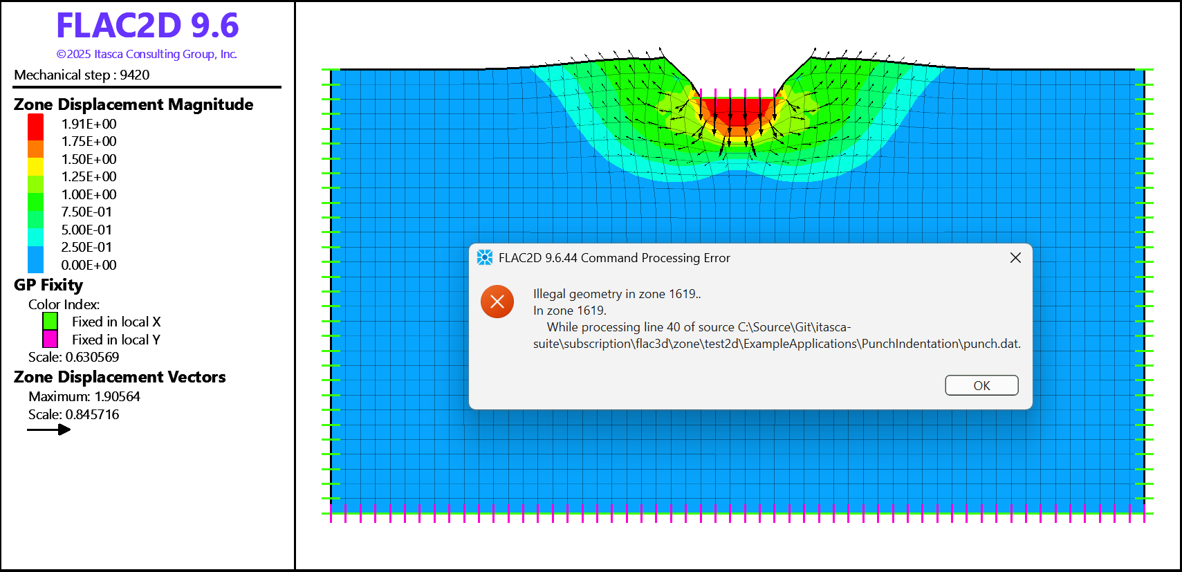
Figure 1: The “Illegal geometry” error is produced if running the model in large strain without remeshing.
FLAC2D Model
The initial geometry and mesh are generated in Sketch and shown in Figure 2. The model is 55 m wide and 30 m deep, and zone size of 1 m is used. The entire model boundary (all edges) is assigned to group “remesh” in slot “Remesh” (green/blue edges in Figure 2); thus, the whole model will undergo remeshing. The punch load is applied over 5 m wide area at the top of the model designated by the group “Load” in slot “Default” (an edge highlighted in blue). Since the edge with group “Load” is also part of the remeshing boundary, it will be preserved during remeshing along with the applied conditions. A constant velocity of 2×10⁻⁴ m/step is specified to apply the loading over the punch area. The model has roller boundary conditions on the sides and is fixed in both directions at the base. The model is run in large-strain mode.
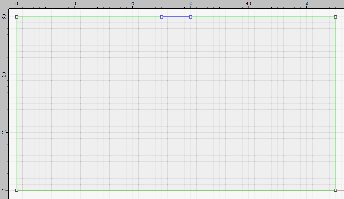
Figure 2: Punch model geometry. Punch load is applied over the edge highlighted in blue.
Figure 3 and Figure 4 show the final model deformation after 120000 steps when remeshing is enabled. The first remeshing occurs at step 8910 when shape quality value for one of the zones drops below the default value of 0.025. Subsequently, many more remeshing steps are automatically executed when zones geometry becomes bad again.
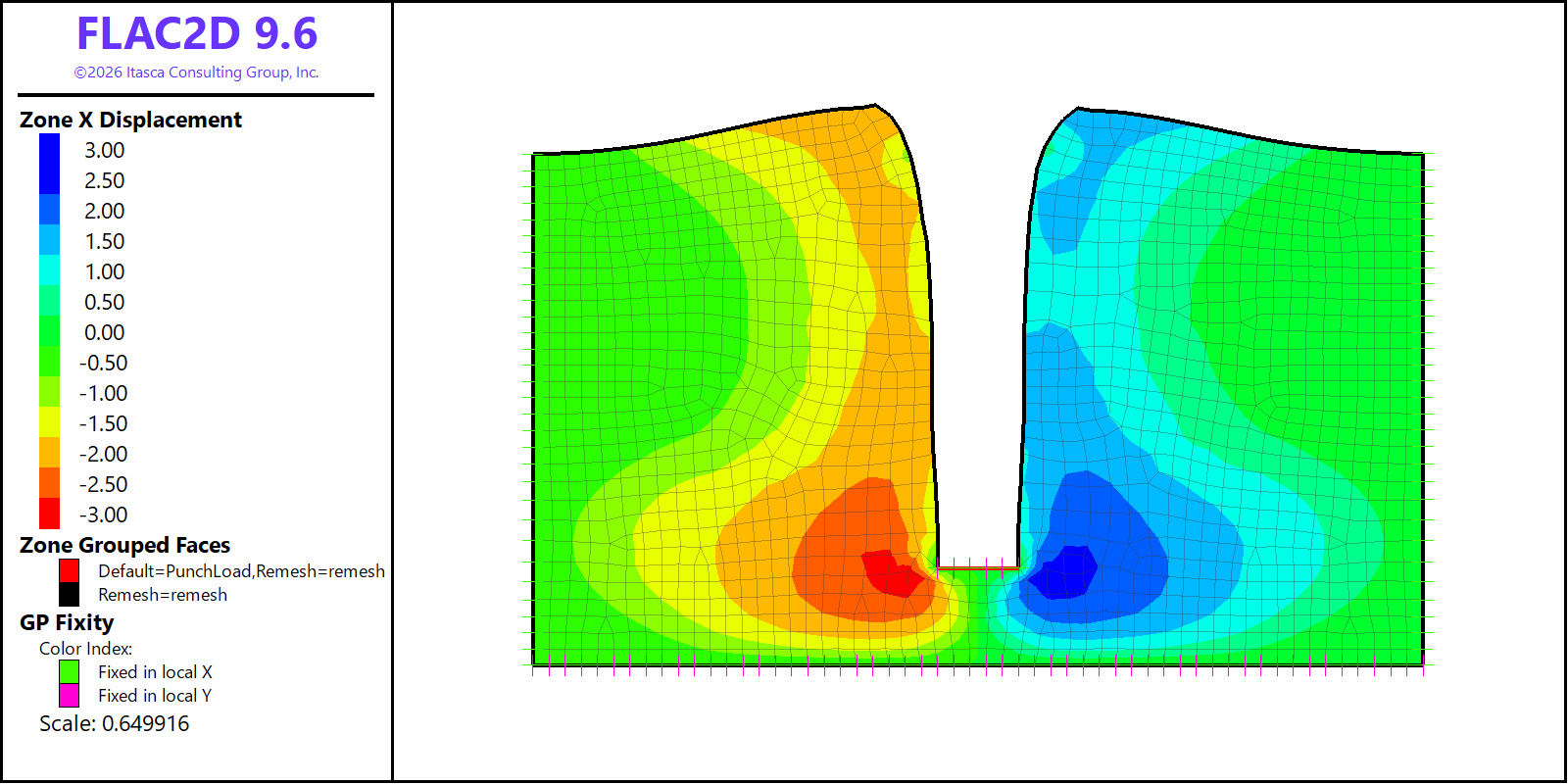
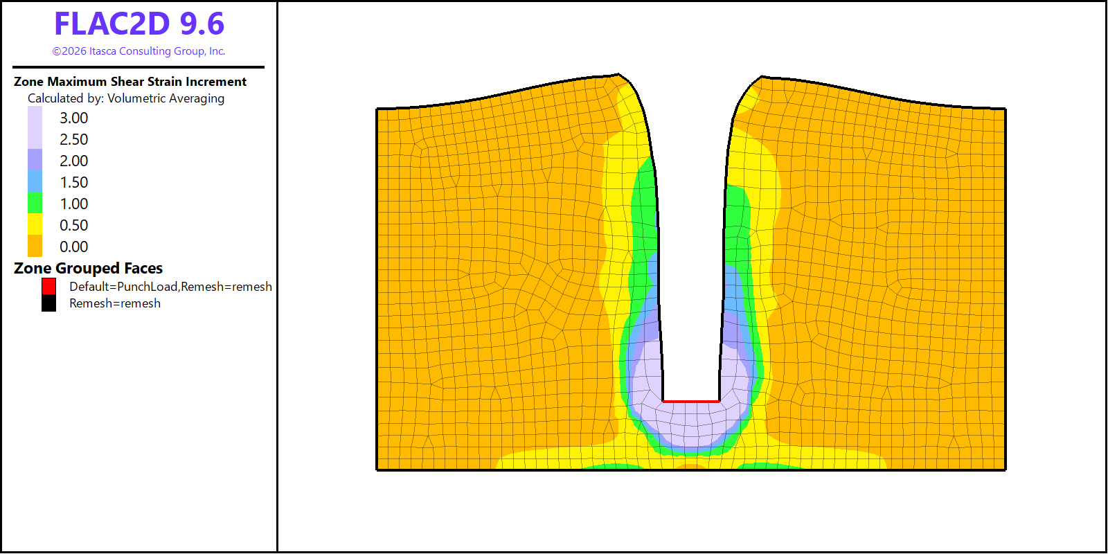
Figure 4: Punch model results after 120000 steps when remeshing is enabled.
The model datafile is shown below.
Note that all sketch commands are provided within the code, however, users may easily create model geometry by drawing it in Sketch. After creating the geometry, it is recommended to save the model state to preserve it or to transfer corresponding commands into a datafile.
The remeshing boundary is defined by the command:
sketch.egde group 'remesh' slot 'Remesh'
The main remeshing commands are provided near the end of the data file:
model remeshing on
zone remesh boundary by-slot 'Remesh'
model new
model large-strain on

; create model geometry and mesh it
sketch set create 'PunchGeometry'
sketch section rectangle point-1 0 0 point-2 55 30
sketch edge id 1 split (25,30)
sketch edge id 6 split (30,30)
sketch edge zone-length 1
; designate edge groups for remeshing
sketch edge group 'remesh' slot 'Remesh'
; designate punch group to apply loading
sketch edge id 1 group 'PunchLoad'
; mesh the geometry
sketch block create automatic
; genereate zones
zone generate from-sketch

; assign constitutive model
zone cmodel mohr-coulomb
zone property density 1000 bulk 2e8 shear 1e8 cohesion 1e5 tension 1e10

; boundary considitions
zone gp fix velocity range position-y 0
zone gp fix velocity-x range position-x 0
zone gp fix velocity-x range position-x 55

; punch loading
zone gp fix velocity-y -2e-4 range group 'PunchLoad'
zone gp fix velocity-x 0 range group 'PunchLoad'

; enable automatic remeshing
model remeshing on
zone remesh boundary by-slot 'Remesh'

; set how frequently plots are updated
model update-interval 100

; run the simulation
model step 120000
Endnote
| Was this helpful? ... | Itasca Software © 2026, Itasca | Updated: Feb 07, 2026 |
