Failure of a Benched Slope
Problem Statement
The project file for this example may be viewed/run in FLAC2D.[1] The main data file used is shown at the end of this example.
A two-bench slope excavated in sensitive clay fails when the excavation level reaches a depth of 9 m. The initial geometry of the slope at this excavation depth is shown in Figure 1. The slope fails due to gravitational loading and slides in rotational and translational regime. The model is run in large strain and if model remeshing is disabled, a “bad geometry” error occurs soon after the slope movement. This example shows how to use the automatic remeshing functionality to allow for uninterrupted simulation of progressive slope failure.
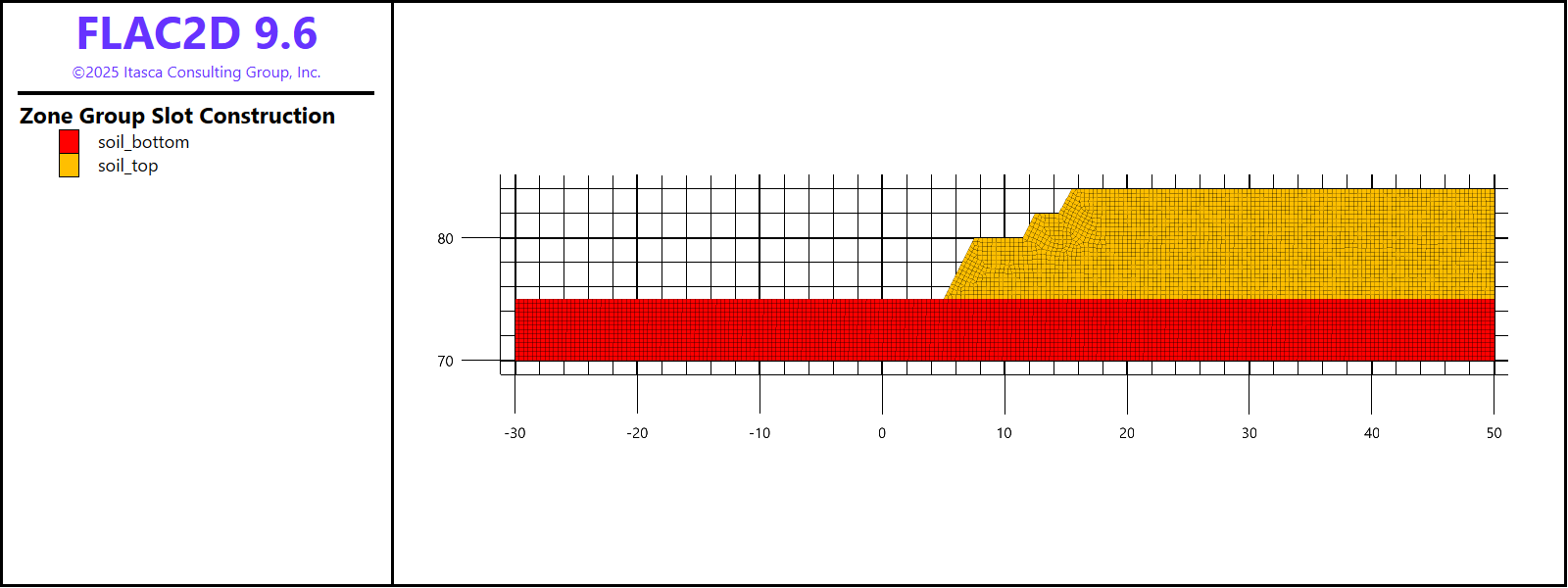
Figure 1: Benched slope geometry (after the excavation).
Model Geometry
The model geometry is created in Sketch using the Slope Wizard tool. After opening the Slope Wizard, fill in the dialog fields as shown in Figure 2. Note that slope angles (e.g., Slope1, Slope2, etc.) are automatically calculated based on the other dimensions. Make sure not to create internal edges.
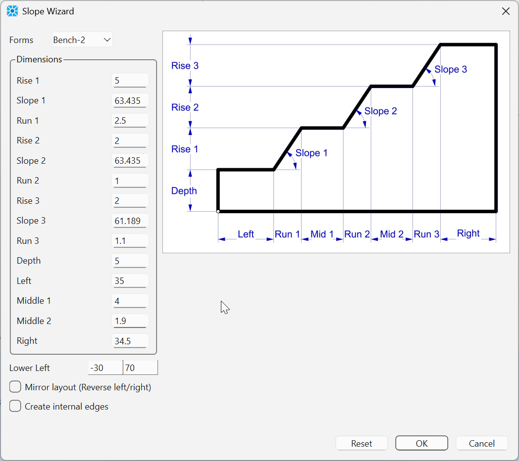
Figure 2: Create slope using the Slope Wizard.
After making the initial slope, create two points by using the Point tool (from the Point/Edge tools menu) or by pressing spacebar (when the Sketch Workspace is active) and typing coordinates. The second approach is more accurate for this model as it allows creating points at exact locations and immediately splits the right edge in the correct proportions. Create the first point at (-30, 84) and the second one at (50, 75), e.g., as in Figure 3.
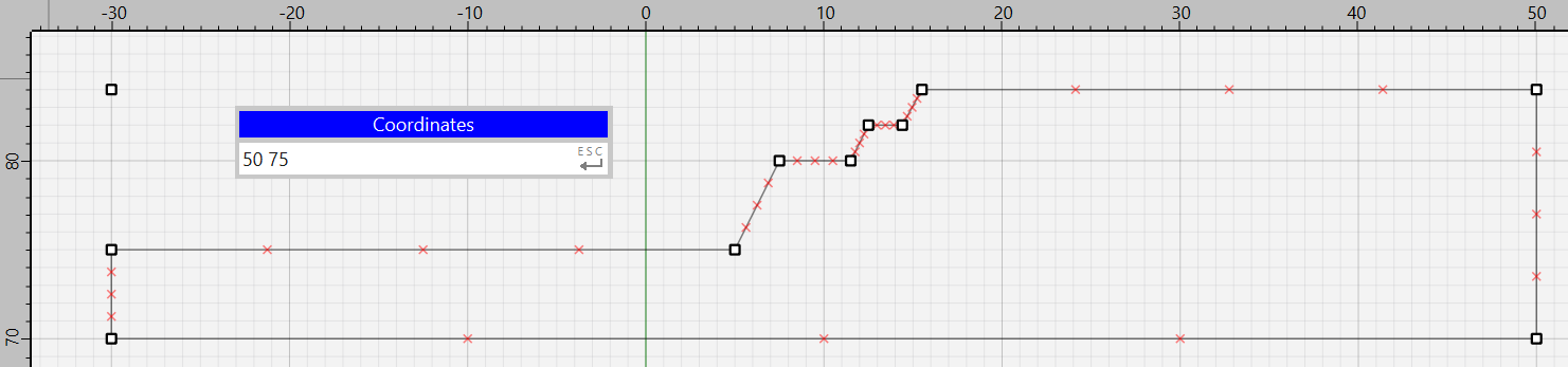
Figure 3: Benched slope geometry building in Sketch.
Next, select the edges forming the bench and the base and assign to them group “remesh” in slot “Remesh”. As this slot is not initially present, delete the name of any other slot from the edit box and type “Remesh”, then type group name. Also, set zone length to 0.35 m as shown in Figure 4. After this, deselect all edges and only select the remaining two edges at the top-left.[2] Set zone length to 0.35 m and do not assign any new groups or slots.
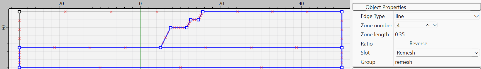
Figure 4: Group and slot assignment to the bench model.
Click on Mesh All Polygons button to create unstructured meshes for the model. Select the top-left block and assign to it group “excavate” in slot “Construction”. Similarly assign group “soil_top” to the top-right block and group “soil_bottom” to the bottom block.
The model geometry is ready; save the model state under the name “geometry.sav”.
Modeling Procedure
The clay exhibits a softening response under load. This behavior is simulated by using the strain-softening constitutive model with the cohesion of the clay above the 9 m depth degrading from 50 kPa to 5 kPa as a function of plastic shear strain. Other properties of the clay are shown below.
mass density (\(\rho\)) |
2000 kg/m3 |
bulk modulus (\(\kappa\)) |
1.7 MPa |
shear modulus (\(G\)) |
0.625 MPa |
initial cohesion (\(c\)) |
50 kPa above 9 m depth |
The strain-softening material model is assigned a special property:
zone property length-calibration 0.592
which specifies an additional calibration of material properties due change in zone sizes during simulations(see details in Strain Softening properties). Initially, all zones have similar size (~0.35m) for this model, but if this is not the case, it is recommended to set the “length-calibration” parameter to the dominant zone size within the initial shear band region.
Prior to the excavation, stresses are initialized based on gravity, assuming the ratio of horizontal to vertical stress 0.65. The excavation is then made instantaneously (using zone delete command). The slope begins to fail. If the model is run without automatic remeshing, an “illegal geometry” error quickly occurs in zones at the toe of the slope after ~ 130 steps.
To ensure more accurate results, the geometry check is done every 5 steps. The model can be run throughout the entire slope failure until it stops, and the model reaches a static equilibrium. The remeshing logic is invoked multiple times for this model for two reasons: (1) zone geometry becomes bad, (2) the slope is “rolling” over the base of the model and zones at the toe of the slope start penetrating and overlapping with zones at the base. Both situations are properly handled by the remeshing logic.
Figure 5 shows the slope failure after 2300 steps. The maximum shear strain contour reveals that slope failure starts with the rotational mechanism. The final shape of the failed slope is shown in Figure 6.
Note that the users may get somewhat different results final shape of the failed slope which is caused by three main reasons. First, the meshing process may produce equivalently valid but slightly different unstructured meshes at remeshing steps. Second interpolating numerous model parameters from the old mesh to a new one leads to data smoothing. And third, the strain-softening material properties depend on the accumulated shear strain and zone size, which makes the model sensitive to how often the geometry and mesh are updated. The overall slope failure, however, is consistent between model runs and the final failed slope shape is in the agreement with those observed in normal slope failure mechanism.
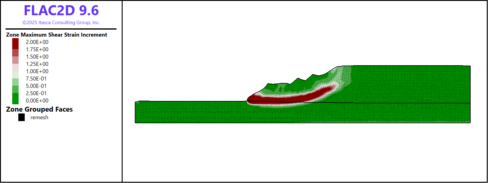
Figure 5: Contours of the maximum shear strain after ~2300 steps.
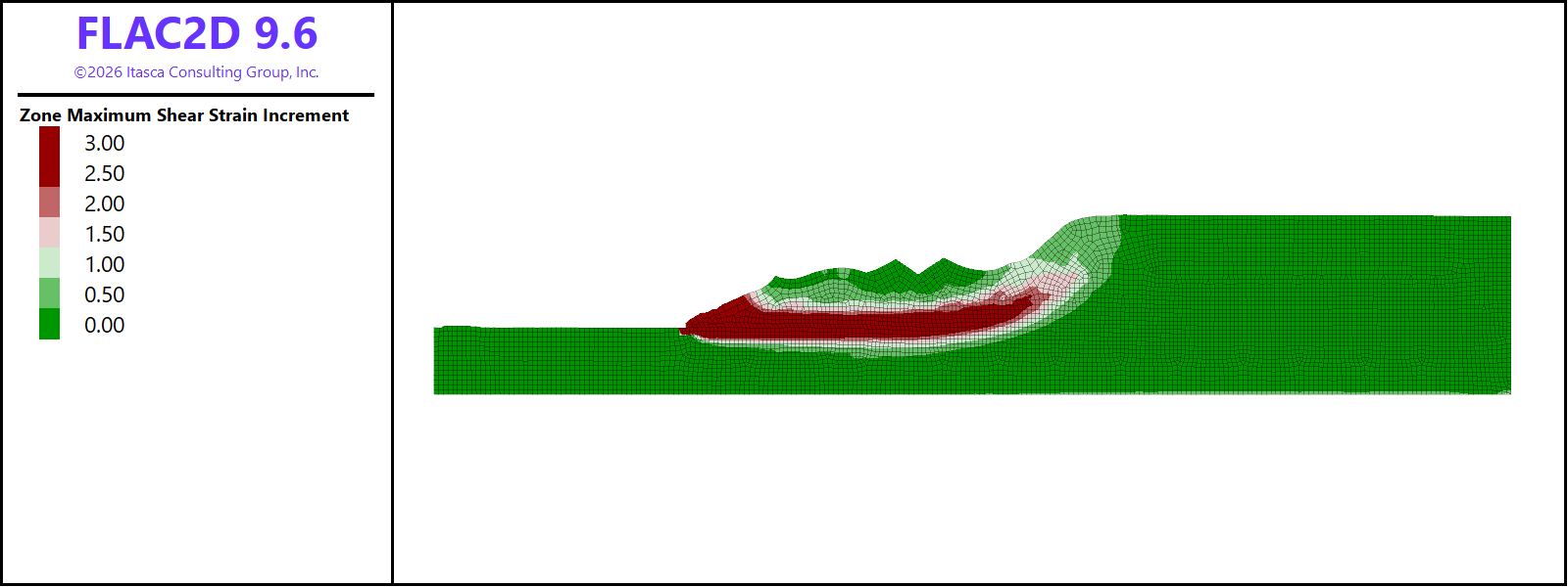
Figure 6: Failed slope after reaching equilibrium.
Data Files
slope2d.dat
model restore 'geometry'

model large-strain off
model gravity 10

; automatically assign groups to model boundaries
zone face skin

; set constitutive model and properties
zone cmodel strain-softening

; table for cohesion - shear strain
table 'coh1' add (0 50e3) (0.05 5e3)
table 'coh2' add (0 70e3) (0.02 70e3)

zone property density 2000 bulk 1.7e6 shear 0.625e6
zone property cohesion 45e3 range group 'soil_top' or 'excavate'
zone property cohesion 70e3 range group 'soil_bottom'
zone property table-cohesion 'coh1' range group 'soil_top' or 'excavate'
zone property table-cohesion 'coh2' range group 'soil_bottom'
; special property - length calibration
zone property length-calibration 0.592

; boundary and initial conditions
zone gridpoint fix velocity-x 0 range group 'East' or 'West'
zone gridpoint fix velocity 0 0 range group 'Bottom'

; initialize stresses
zone initialize-stresses ratio 0.65

; solcve to initial equilibrium
model solve convergence 1
model save 'initial'

; instantaneously "excavate" zones
zone delete range group 'excavate'

; switch to large strain
model large-strain on

; fix left boundary
zone gridpoint fix velocity 0 0 range group 'West'

; set the remeshing logic
model remeshing on
zone remesh boundary by-slot 'Remesh'

; set geometry and model (plotting) update intervals
zone geometry update-interval 5
model update-interval 50

; solve to equilibrium
model solve convergence 1

model save 'slope_final'
Endnote
| Was this helpful? ... | Itasca Software © 2026, Itasca | Updated: Feb 07, 2026 |
