Automatic Remeshing in FLAC2D
Note
Automatic remeshing is a BETA functionality.[1]
When running a FLAC2D analysis in the large-strain mode, zones may deform significantly, which may lead to bad or “illegal” geometry errors. Such errors indicate that numerical calculations cannot be done in such zones, and analysis is aborted. The remeshing functionality is designed to address these issues and allow users to continue numerical simulations. The remeshing logic is automatically invoked if any of the following occurs:
zone area becomes zero or negative (e.g., inverted quadrilateral zone),
the area of any of internal subzones becomes zero or negative,
all internal zone overlays are deleted,
the ratio of the smallest internal subzone area to zone area is less than zone tolerance set by
zone geometry tolerancecommand (tolerance = 0 by the default),zone 2D shape quality is less than the minimum value set by
zone remesh shape-qualitycommand (min value = 0.025 by the default),zones overlapping or interpenetration between different remeshing regions is detected.
All these criteria are checked every 10 steps (by the default) or at the intervals set by the user with zone geometry update-interval command.
FLAC2D remeshing logic is based on several main steps.
Before cycling the model, the user must define closed boundaries (remeshing domains) within which remeshing will take place, if needed. Typically, the whole model is remeshed, and in such a case, its exterior boundaries can be set as the remeshing boundaries. In some cases, however, it is possible to define remeshing of smaller regions (e.g., as described in Defining Remeshing Domains/Boundaries below).
All necessary gridpoint, zone, and face parameters are preserved in temporary storage.
The remeshing logic automatically recreates a mesh within the specified remeshing boundaries and replaces old bad meshes with new good meshes. An unstructured mesh type is always used when creating a new mesh.
The remeshing logic copies and/or interpolates all necessary data from the temporary storage to all gridpoints, zones, and faces within newly created meshes.
Model cycling continues.
Steps to set up remeshing
The first three items below are required to enable automatic remeshing.
Define remeshing domains / boundaries.
Configure model for remeshing (this can be done at the beginning, before cycling, or before expecting bad geometry):
Specify which Slot contains the remeshing boundaries (for example,
"MyRemeshingSlot"):zone remesh boundary by-slot"MyRemeshingSlot"Optional: Specify other
zone remeshoptions.Optional: Specify geometry check / update interval if different from the default (every 10 steps). Depending on the model and the severity of deformations, it may be necessary to set more frequent geometry checks (sometimes as frequent as every 3 - 5 steps). Note that more frequent geometry checks may increase model runtime.
Optional: In rare cases involving large and fast-developing deformations, it may be necessary to increase the mechanical safety factor to allow FLAC2D to make smaller increments in system damping when solving EOM. This will allow for more incremental geometry changes and can lead to more accurate and stable results. See
zone mechanical safety-factorcommand.
After this, start or continue model cycling.
Considerations
Defining Remeshing Domains/Boundaries
The first step in using the remeshing functionality is to define a domain (or multiple domains) in which remeshing will take place. The domains are defined by closed boundaries represented by named/grouped faces. All such groups must be assigned to a unique SLOT, as the remeshing logic will use every group from this slot to identify the boundaries.
There are two main ways of creating face groups while assigning them to a remeshing slot:
Define groups directly using command
zone face groupand Range logic, for example:zone face group "MyGroup" slot "Remesh" range ...If model geometry is created via Sketch, users may directly create remeshing boundaries by assigning groups and slots to edges.
The remeshing groups and the Slot may have any names (e.g., “MyGroup”, “Remesh”). Only the slot name is used to identify the remeshing domains / boundaries as discussed earlier. Several possible cases of defining remeshing boundaries are shown next.
Remeshing the whole model using the exterior boundaries.
As the interior model boundaries are located within the remeshing domain but not assigned to the remeshing Slot, they will be deleted during the remeshing step.
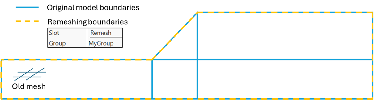
Figure 1: Model boundaries before remeshing.
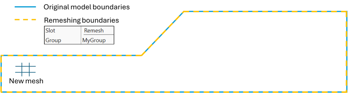
Figure 2: Model boundaries after remeshing.
Remeshing the whole model and preserving internal boundaries.
In many cases it is important to preserve internal boundaries during remeshing. Such boundaries may separate different materials; thus, it would be important to preserve separate domains (e.g., soil / rock layers below).
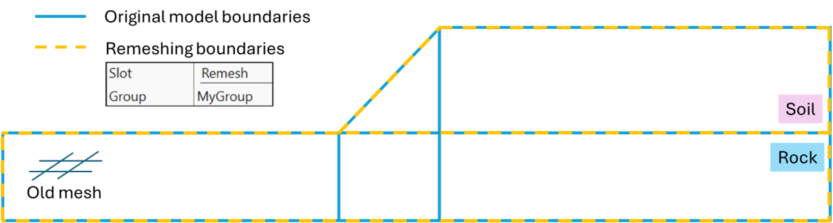
Figure 3: Two-layer model boundaries before remeshing.
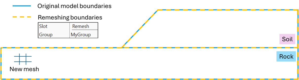
Figure 4: Two-layer model boundaries after remeshing.
Remeshing a part of the model and preserving the boundary between domains.
IMPORTANT: it is only advised to make remeshing domain smaller than the whole model when deformations (strains, stresses) at the parts of the remeshing boundaries located within the model (e.g., within the red ellipses below) are insignificant or very small. Certain constitutive models may produce inaccurate results and even artificial failure at such boundaries due to small discrepancies between interpolated and not interpolated zone / gridpoint data when deformations occur at such boundaries.
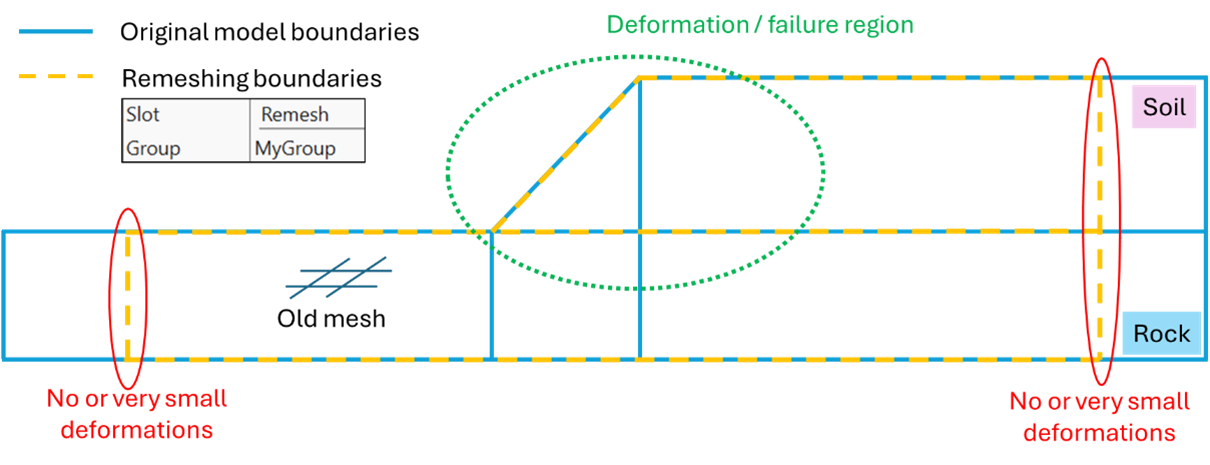
Figure 5: Two-layer model before remeshing with remeshing boundaries defined on a portion of the model.
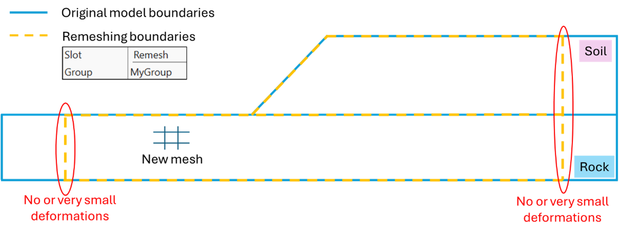
Figure 6: Two-layer model after remeshing with remeshing boundaries defined on a portion of the model. Model parts outside of the remeshing domain are not altered.
Gridpoint Fixity And Face Apply Conditions
All gridpoints with set fixity or initial conditions as well as the conditions (e.g., set with zone gridpoint fix, zone gridpoint initialize) are preserved during remeshing.
Zone faces with apply conditions (e.g., set with zone face apply) which are located on the remeshing boundaries are preserved.
Zone faces with groups/slots other than the remeshing slot retain all the groups/slots, if they are located on the remeshing boundaries.
Note that parts of the remeshing boundaries containing any fixity or apply conditions are not altered. If such boundaries significantly deform, it may lead to creation of bad meshes at the boundaries and potential remeshing failure.
Smoothing/Preserving Model Boundaries
The shape and discretization of the remeshing boundaries located on the exterior of the model are preserved as much as possible. This is needed to avoid smoothing any existing model features and to preserve fixity and apply conditions typically configured on the exterior model boundaries. If free faces (no BCs) on the exterior remeshing boundaries are significantly stretched, they may be re-discretized/split into smaller segments to avoid creation of very large zones (compared to the average model zone size). However, smaller zones/faces on the exterior boundaries are not modified to create larger zones.
Remeshing boundaries located within the domain are smoothed and re-discretized to provide better meshing results. Parts of the internal remeshing boundaries containing gridpoints and faces with fixity and/or apply conditions are preserved.
If gridpoints on the exterior model boundaries significantly pinch out due to large deformations and create very thin “spikes”, such “spikes” may be truncated. See more details in zone remesh boundary pinchout-angle. This option must be used carefully, as artificial removal of a part of the model may lead to instability. If this option is not desired, set the pinch-out angle to 0.
Choosing Appropriate Geometry Update Interval
The default geometry update interval under large-strain is every 10 steps. During these updates, remeshing logic checks if the remeshing logic needs to be triggered. Thus, it may seem reasonable to have geometry checks more frequently. This, however, is not recommended for a few reasons: (1) the analysis will be slower, (2) frequent interpolations may introduce inaccuracies in the solution and even alter model behavior, and (3) after each remeshing step it is recommended for the model to cycle at least for a few steps to equilibrate stresses, strains, etc. On the other hand, rather infrequent geometry checks may not catch in time the occurrence of bad zones in the model.
Recommended geometry check interval is every 3 – 10 steps but it depends on each model.
Current Limitations
Current limitations of the remeshing functionality include:
No support for Structural Elements
No support for interfaces or zone joints
Attach conditions are not allowed
Axisymmetry is not allowed
No interpolation between FISH extra variables (however, new gridpoints and zones may receive a direct copy of such parameters from the nearest gridpoints / zones in the old mesh)
Remeshing boundaries with fixity and apply conditions are not adjusted / reconfigured even if significantly deformed
Depending on the geometry, the meshing logic may produce valid but non-deterministic unstructured meshes. This means that modeling results may not be fully deterministic (also depends on constitutive models used and how sensitive they are to zone shapes/sizes). However, overall modeling results are always consistent.
Many of these limitations will be resolved with future updates and releases.
Remeshing Examples
Endnote
| Was this helpful? ... | Itasca Software © 2026, Itasca | Updated: Feb 07, 2026 |
