Slope Stability: Comparison to Fredlund and Krahn (1977) Study
This example reproduces example 1.4.2 from the FLAC/Slope 8.1 manual. The project file for this example may be viewed/run in FLAC2D.[1] The main data file used is shown at the end of this example.
Problem Statement
Fredlund and Krahn (1977) report a comparison of several different limit equilibrium methods for the solution of a slope stability example involving different combinations of slope material and piezometric conditions. The conditions are shown in Figure 1. Four of the cases analyzed by Fredlund and Krahn (1977) are reanalyzed with FLAC2D. The descriptions of these cases are:
Case 1: Simple 2:1 slope, 40 ft high, φ = 20°, c = 600 psf, no weak layer, no bedrock
Case 2: Same as Case 1 with thin weak layer (φ = 10°, c= 0) and bedrock
Case 5: Same as Case 1 with piezometric line
Case 6: Same as Case 2 with piezometric line
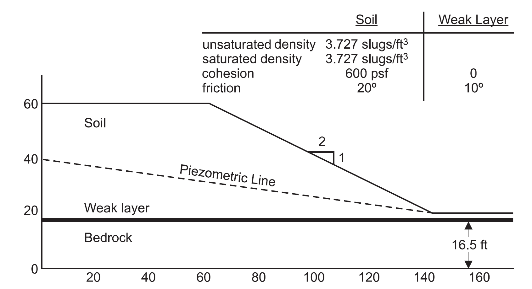
Figure 1: Slope stability example (from Fredlund and Krahn 1977).
FLAC2D Model
The model is built in Sketch. The Slope wizard is used with the following inputs:
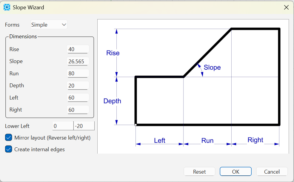
Note that you can enter the Rise and Run and the Slope angle is calculated automatically. A horizontal line is drawn at y = -3.5 to represent the boundary between soil and bedrock. The model is zoned with a zone size of 2.5 and a minimum of 2 zones per edge. Group names are assigned the to soil layer and the bedrock layer, as well as to the edge on the boundary between the layers. Zones are generated and the model appears as in Figure 3.
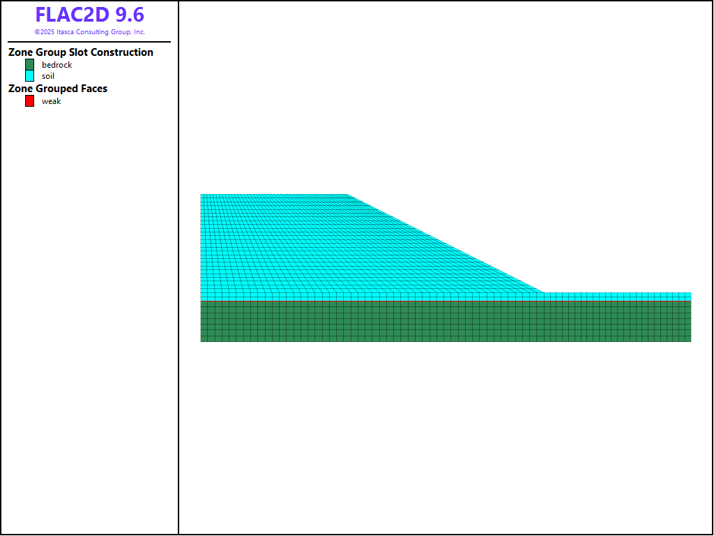
Figure 3: Model used in slope stability simulation
For case 2 and 6, the weak layer is simulated with a zone joint. For cases 5 and 6, the water table is simulated by creating a geometry that defines the water table and using the command zone gridpoint pore-pressure geometry. Note that the cutoff keyword is used to prevent negative pore pressures above the water table. The pore pressures for case 6 are shown in Figure 4
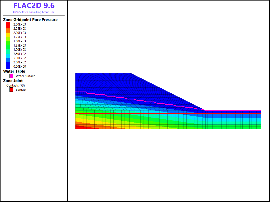
Figure 4: Pore pressures, water table and zone joint for case 6 model
Results
The Factors of Safety for each case compared to the study of Fredlund and Krahn (1977) are shown in Table 1. The FLAC2D results are in good agreement with the results from the limit equilibrium calculations.
The result of the FOS calculation for case 6 is shown in Figure 5.
Case |
Simplified Bishop |
Spencer’s |
Janbu’s Rigorous |
Morgenstern-Price |
FLAC2D |
|---|---|---|---|---|---|
1 |
2.08 |
2.07 |
2.01 |
2.08 |
2.00 |
2 |
1.38 |
1.37 |
1.43 |
1.38 |
1.37 |
5 |
1.83 |
1.83 |
1.78 |
1.83 |
1.79 |
6 |
1.25 |
1.25 |
1.30 |
1.25 |
1.23 |
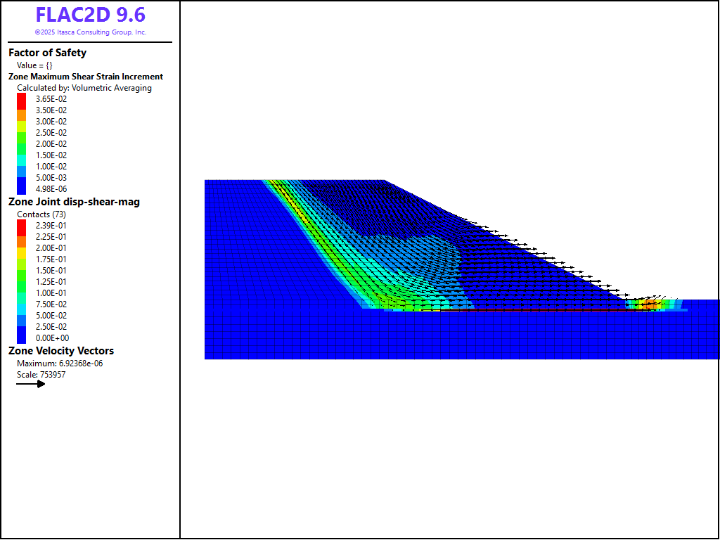
Figure 5: Factor of safety results for case 6.
References
Fredlund, D. G., and J. Krahn. “Comparison of Slope Stability Methods of Analysis,” Can. Geotech. J., 14, 429-439 (1977).
Data Files
case1.dat
model restore 'sketch'

model gravity 32.18504
model large-strain off

zone cmodel assign mohr-coulomb

zone property density 3.727 bulk 2.0E6 shear 6.3E5 ...
              cohesion 600.0 friction 20.0 dilation 0.0 tension 1.0E10

zone face skin
zone face apply velocity-x 0 range group 'East' or 'West'
zone face apply velocity (0,0) range group 'Bottom'

model factor-of-safety filename 'case1'
case2.dat
model restore 'sketch'
model gravity 32.18504
model large-strain off

zone cmodel assign mohr-coulomb range group 'soil'
zone property density 3.727 bulk 2.0E6 shear 6.3E5 ...
              cohesion 600.0 friction 20.0 dilation 0.0 tension 1.0E10 ...
              range group 'soil'

zone cmodel assign elastic range group 'bedrock'
zone property density 3.727 bulk 2.0E7 shear 6.3E7 ...
              range group 'bedrock'

zone face skin
zone face apply velocity-x 0 range group 'East' or 'West'
zone face apply velocity (0,0) range group 'Bottom'

zone separate by-face range group 'weak'
zone joint configure
zone joint create by-face range  group 'weak'
contact property stiffness-shear 1.0E7 stiffness-normal 1.0E7 ...
                             friction 10

model factor-of-safety zone-joint include 'friction' filename 'case2'
case5.dat
model restore 'sketch'
model gravity 32.18504
model large-strain off

zone cmodel assign mohr-coulomb

zone property density 3.727 bulk 2.0E6 shear 6.3E5 ...
              cohesion 600.0 friction 20.0 dilation 0.0 tension 1.0E10

zone fluid-density 1.94

; make geometry set to define plane
geometry set 'water_table'
geometry edge create by-positions (0,20.0) (140.0,0.0) (200.0,0.0)

; set water table. Pore pressures will be calculated
zone gridpoint pore-pressure geometry 'water_table' cutoff

zone face skin
zone face apply velocity-x 0 range group 'East' or 'West'
zone face apply velocity (0,0) range group 'Bottom'

model factor-of-safety filename 'case5'
case6.dat
model restore 'sketch'
model gravity 32.18504
model large-strain off

zone cmodel assign mohr-coulomb range group 'soil'
zone property density 3.727 bulk 2.0E6 shear 6.3E5 ...
              cohesion 600.0 friction 20.0 dilation 0.0 tension 1.0E10 ...
              range group 'soil'

zone cmodel assign elastic range group 'bedrock'
zone property density 3.727 bulk 2.0E7 shear 6.3E7 ...
              range group 'bedrock'

zone face skin
zone face apply velocity-x 0 range group 'East' or 'West'
zone face apply velocity (0,0) range group 'Bottom'

zone separate by-face range group 'weak'
zone joint configure
zone joint create by-face range  group 'weak'
contact property stiffness-shear 1.0E7 stiffness-normal 1.0E7 ...
                             friction 10

zone fluid-density 1.94

; make geometry set to define plane
geometry set 'water_table'
geometry edge create by-positions (0,20.0) (140.0,0.0) (200.0,0.0)

; set water table. Pore pressures will be calculated
zone gridpoint pore-pressure geometry 'water_table' cutoff

model factor-of-safety zone-joint include 'friction' filename 'case6'
Endnote
| Was this helpful? ... | Itasca Software © 2026, Itasca | Updated: Feb 07, 2026 |
