Homogeneous Slope at Failure (FLAC2D)
This example reproduces example 1.4.1 from the FLAC/Slope 8.1 Manual.The project file for this example may be viewed/run in FLAC2D.[1] The main data file used is shown at the end of this example.
Problem Statement
This example compares FLAC2D to a limit analysis solution given by Chen (2007). The problem setting is a homogeneous embankment of height H = 10 m, slope angle 45 degrees, unit weight γ = 20 kN/m3, cohesion c = 12.38 kPa and friction angle 20 degrees. A gravitational acceleration of 10.0 m/sec3 is also specified. For these parameters, Chen calculates a factor of safety of exactly 1.0. This example problem is also presented in the publication by Dawson et al. (1999), which compares and validates the FLAC solution for several variations of the homogeneous embankment conditions.
Model Geometry
The model zones are created in a sketch using the Slope Wizard tool. After opening the slope wizard, fill in the form as shown in Figure 1.
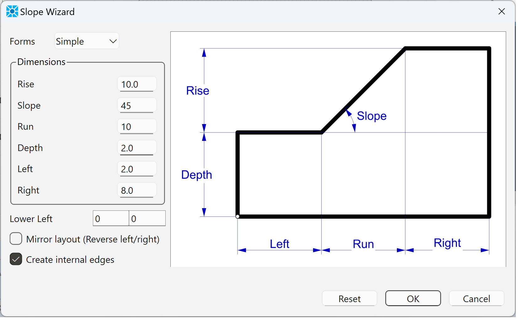
Figure 1: Slope Geometry.
Next use autosize (![]() ) on the “Mesh Tools” pulldown to set zone length to 0.25. Then use mesh all polygons (
) on the “Mesh Tools” pulldown to set zone length to 0.25. Then use mesh all polygons (![]() ), also on the “Mesh Tools” pulldown, to add zones to the model blocks. Finally, press the create zones button (
), also on the “Mesh Tools” pulldown, to add zones to the model blocks. Finally, press the create zones button (![]() ) to create the zones. The model should appear as shown Figure 2 below.
) to create the zones. The model should appear as shown Figure 2 below.
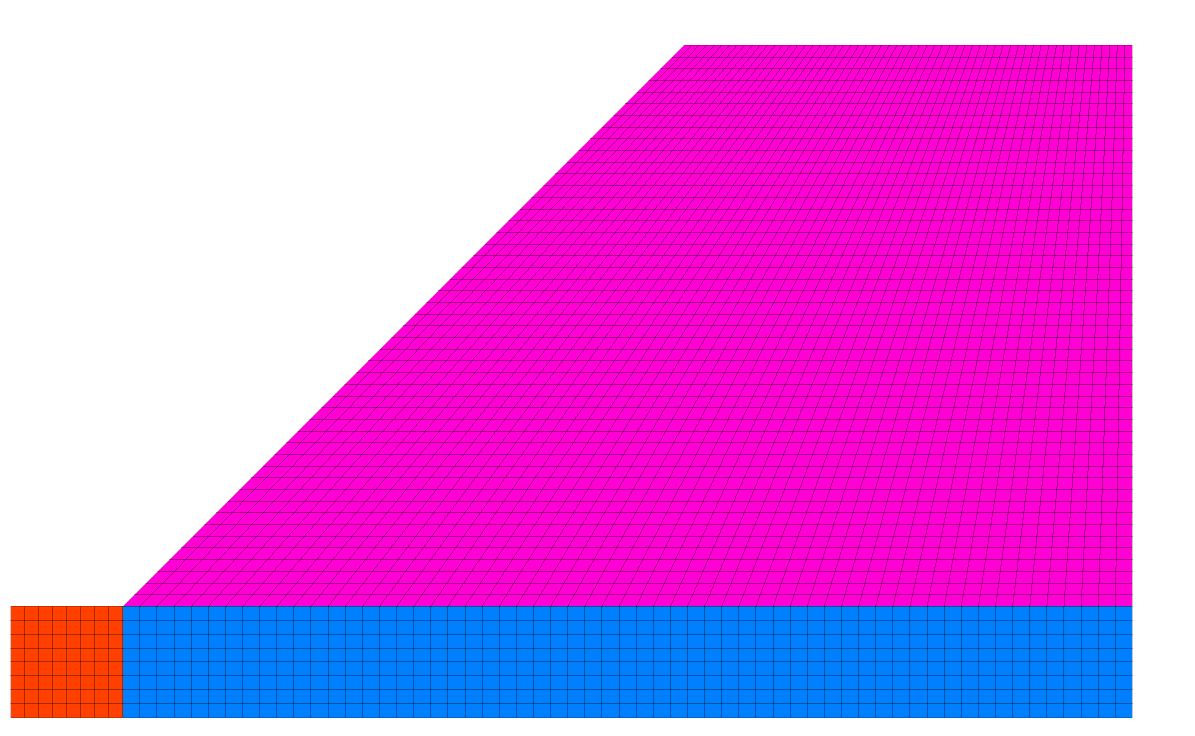
Figure 2: Homogeneous embankment.
From the Model view in the workspace, select all of the zones (ctrl-A), select assign a constituive model… ( ) from the “Commands” pulldown and assign the Mohr-Coulomb constitutive model. Then, with all zones still selected, select set model properties … (
 ) from the same pulldown to assign properties as shown Figure 3 below.
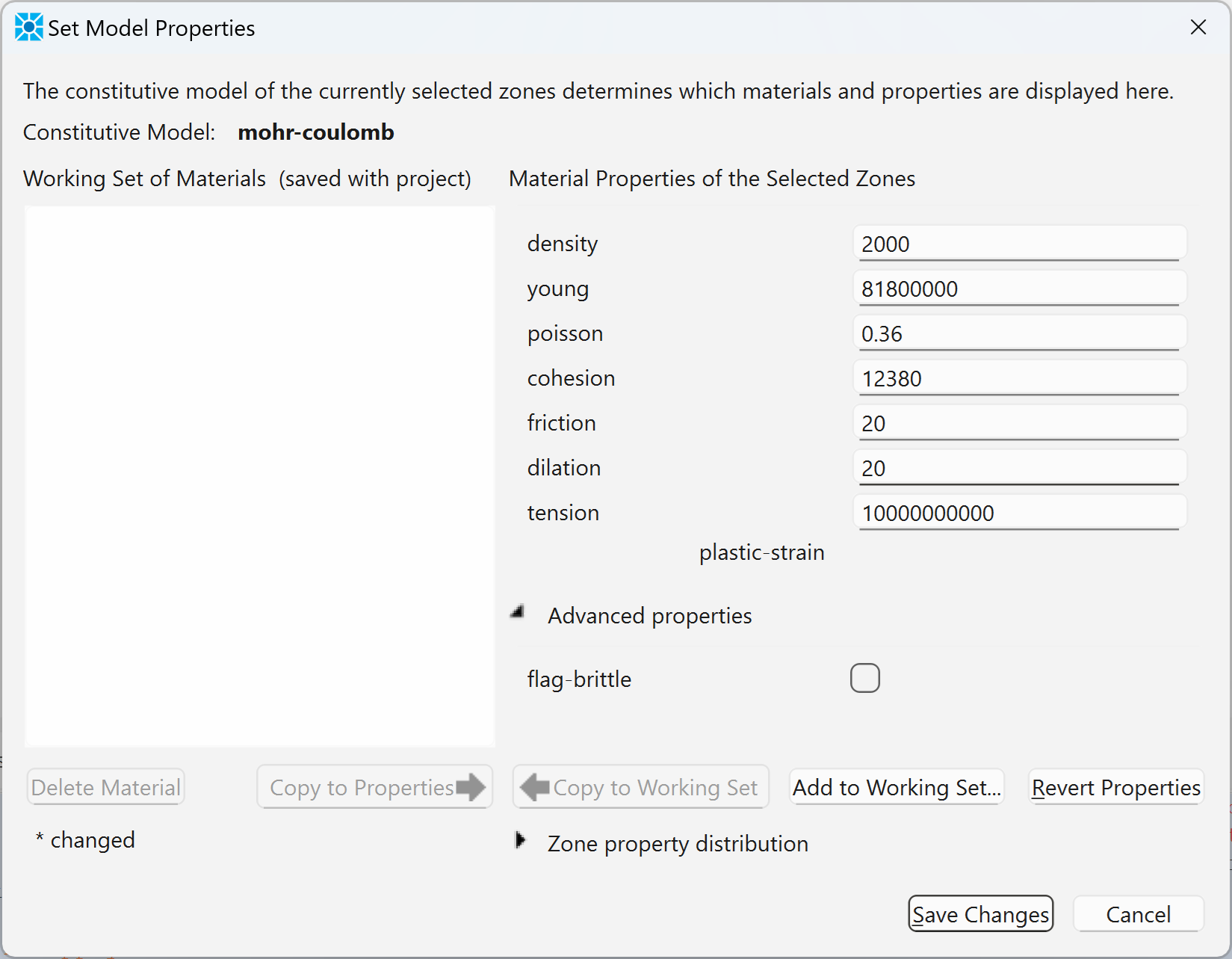
Figure 3: Material properties for homogeneous embankment example.
Note that the limit analysis solution by Chen assumes that the material behavior corresponds to the Mohr-Coulomb yield criterion with an associated flow rule (dilation angle ψ = φ). Also, the tensile strength of the material is set to a high value to prevent use of the tension cutoff, for comparison to the Chen solution.
Next, click the button on the toolbar to “Assign group names to faces automatically”. In the resulting dialog, check the box to “Ignore existing group names” as shown:
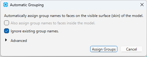
The will automatically assign group names to the outer edges for use later when applying boundary conditions. Finally, save the model state as “geometry.sav.” This file can then be restored as a starting point for the FOS analysis. Alternatively, click on the State Record tab above the console, right-click inside the window and select “Save to file as data file”. This data file can then be called to build the model and assign the properties as shown in chen.dat.
Model Solution
The data file below shows how to set gravity and boundary conditions and run the factor-of-safety analysis. The calculated factor-of-safety is 1.01 (within 1% of the solution of Chen). The failure surface is shown in Figure 5.
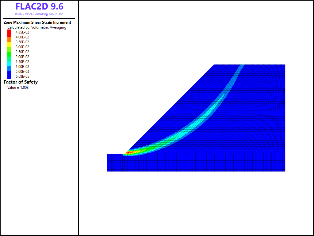
Figure 5: Failure surface calculated for homogeneous embankment.
References
Chen, W.-F. Limit Analysis and Soil Plasticity. J. Ross Publishing (2007).
Data Files
chen.dat
model new
; Commands from Sketch and Model Pane
program call 'geometry.dat'
model configure
model large-strain off
model gravity 0 -10
;
zone face apply velocity-x 0 range union group 'West' group 'East'
zone face apply velocity (0,0) range group 'Bottom'
model factor-of-safety filename 'chen'
Endnote
⇐ Free Vibration Analysis of a Dam (FLAC2D) | Slope Stability: Comparison to Fredlund and Krahn (1977) Study ⇒
| Was this helpful? ... | Itasca Software © 2026, Itasca | Updated: Feb 07, 2026 |
