Slope with a Thin, Weak Layer (FLAC2D)
This example reproduces example 1.4.3 from the FLAC/Slope 8.1 manual. The project file for this example may be viewed/run in FLAC2D.[1] The main data file used is shown at the end of this example.
Problem Statement
A clay slope contains a thin layer of weaker material, which is located within the slope, as shown in Figure 1. The cohesion of the weak plane (\(c_l\) = 10,000 Pa) is 20% of the cohesion of the clay (c = 50,000 Pa). The strength of the weak plane is varied, while the strength of the clay is kept constant, to evaluate the effect of the weak plane on the resulting failure surface and the calculated factor-of-safety. This example is taken from the slope stability study presented by Griffiths and Lane (1999).
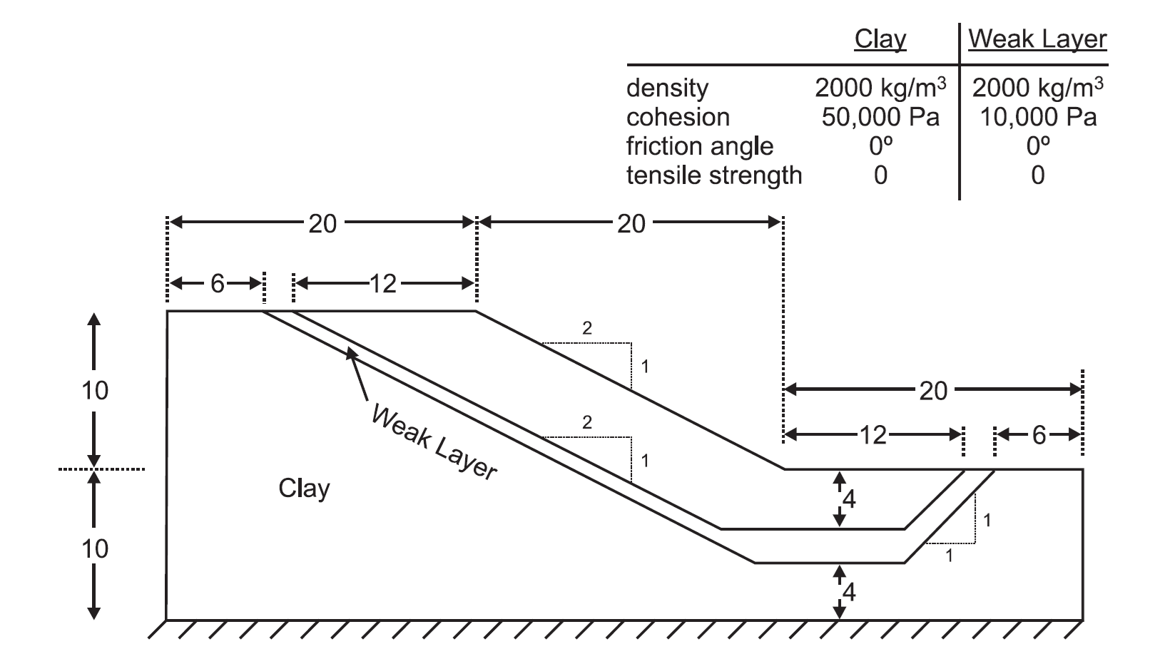
Figure 1: Clay slope containing a thin weak layer (from Griffiths and Lane 1999).
Model Geometry
The model is constructed in Sketch by first using the Slope Wizard with the following settings.
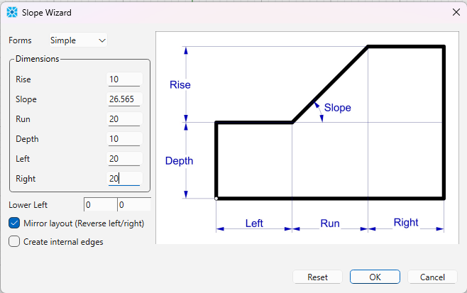
Note that only the Rise and Run need to be entered; the Slope angle is calculated automatically. Note also that “Create internal edges” has been unchecked.
Next, the polyline tool is used to draw lines delineating the weak layer. The bottom line has the following coordinates: (6,20), (38,4), (48,4), (54,10).
The top line has these coordinates: (8,20), (36,6), (48,6), (52,10).
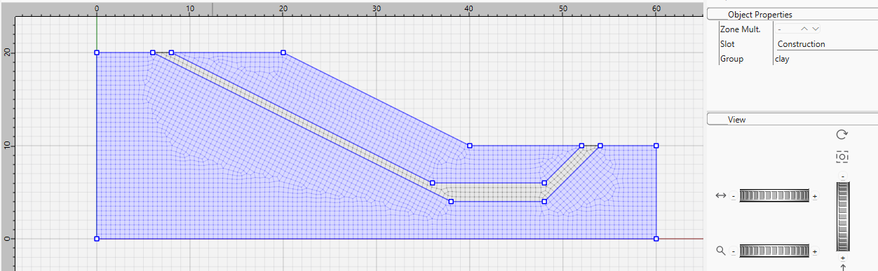
After drawing the lines, mesh the model with a zone size of 0.5. Now select the clay parts of the model and assign the group name “clay” as shown.
Finally, select the thin layer and assign the group name “weak layer” as shown.
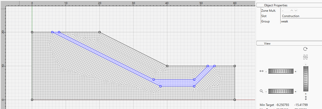
Generate the zones and save the model. If you plot the zones and change the group slot to “Construction” the model will appear as in Figure 5.
Three cases are now analyzed: \(c_l/c\) = 0.2, 0.6 and 1.0.
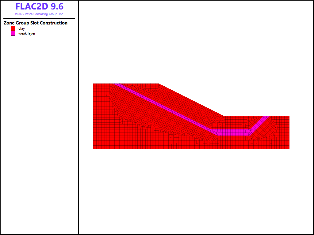
Figure 5: The model showing different soil groups.
Results
The factor-of-safety plots for the three cases are shown in the figures below. The shear strain contour plots in the three figures illustrate the different failure surfaces that develop as the strength of the weak plane is changed. In Figure 6, the failure surface indicates localized slip along the weak plane, while in Figure 8, a circular failure surface develops in the homogeneous material. Figure 7 shows a combination of both weak plane failure and circular-slip failure. All of these results compare directly to those reported in the study by Griffiths and Lane (1999).
The safety factors calculated by FLAC2D for these three cases also correspond to those presented by Griffiths and Lane (1999). The factor is found to drop significantly as the strength of the weak plane is reduced. The case of \(c_l/c\) = 0.6 is shown by Griffith and Lane to be the strength ratio at which there is a transition from the weak-plane failure mode to the circular failure mode.
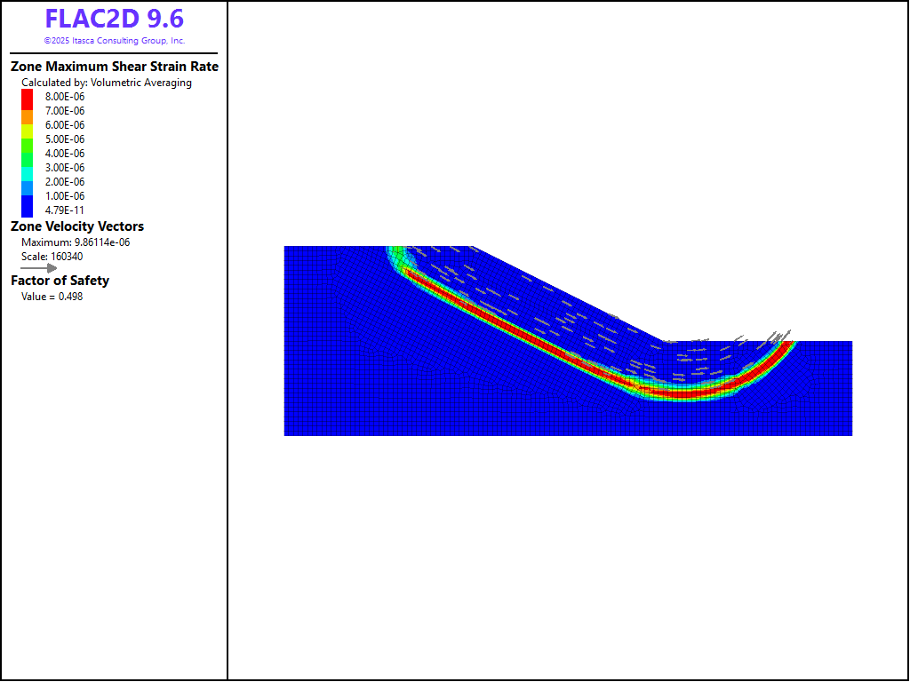
Figure 6: Factor-of-safety plot for \(c_l/c\) = 0.2.
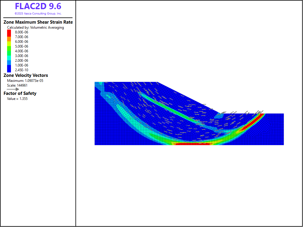
Figure 7: Factor-of-safety plot for \(c_l/c\) = 0.6.
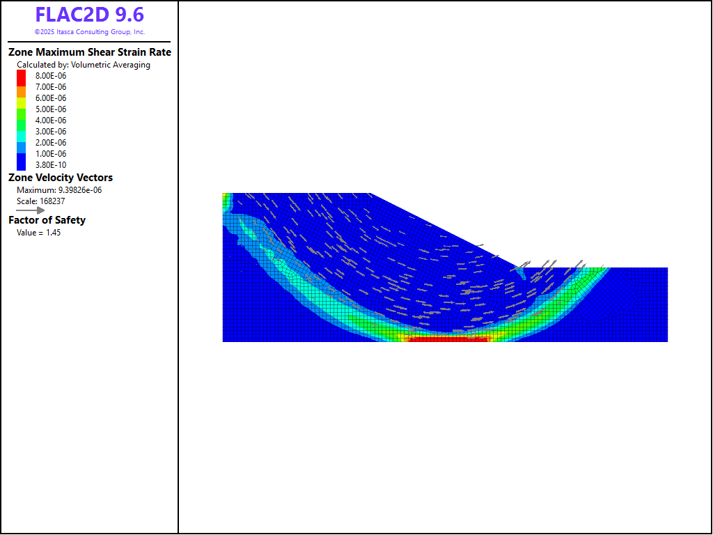
Figure 8: Factor-of-safety plot for \(c_l/c\) = 1.0.
Reference
Griffiths, D. V., and P. A. Lane. “Slope Stability Analysis by Finite Elements,” Géotechnique, 49(3), 387-403 (1999).
Data Files
weaklayer1.dat
model restore 'sketch'

model gravity 9.81
model large-strain off

zone cmodel assign mohr-coulomb

zone property density 2000.0 bulk 1E8 shear 3E7 ...
              cohesion 50000.0 friction 0.0 dilation 0.0 tension 0.0 ...
              range group 'clay'
zone property density 2000.0 bulk=1E8 shear=3E7 cohesion=10000.0 ...
              friction=0.0 dilation=0.0 tension=0.0 range group 'weak layer'

zone face skin
zone face apply velocity-x 0 range group 'East' or 'West'
zone face apply velocity (0,0) range group 'Bottom'

model factor-of-safety filename 'weaklayer1'
weaklayer2.dat
model restore 'sketch'

model gravity 9.81
model large-strain off

zone cmodel assign mohr-coulomb

zone property density 2000.0 bulk 1E8 shear 3E7 ...
              cohesion 50000.0 friction 0.0 dilation 0.0 tension 0.0 ...
              range group 'clay'
zone property density 2000.0 bulk=1E8 shear=3E7 cohesion=30000.0 ...
              friction=0.0 dilation=0.0 tension=0.0 range group 'weak layer'

zone face skin
zone face apply velocity-x 0 range group 'East' or 'West'
zone face apply velocity (0,0) range group 'Bottom'

model factor-of-safety filename 'weaklayer2'
weaklayer3.dat
model restore 'sketch'

model gravity 9.81
model large-strain off

zone cmodel assign mohr-coulomb

zone property density 2000.0 bulk 1E8 shear 3E7 ...
              cohesion 50000.0 friction 0.0 dilation 0.0 tension 0.0 ...
              range group 'clay'
zone property density 2000.0 bulk=1E8 shear=3E7 cohesion=50000.0 ...
              friction=0.0 dilation=0.0 tension=0.0 range group 'weak layer'

zone face skin
zone face apply velocity-x 0 range group 'East' or 'West'
zone face apply velocity (0,0) range group 'Bottom'

model factor-of-safety filename 'weaklayer3'
Endnote
⇐ Slope Stability: Comparison to Fredlund and Krahn (1977) Study | Slope with Geogrid Reinforcement (FLAC2D) ⇒
| Was this helpful? ... | Itasca Software © 2026, Itasca | Updated: Feb 07, 2026 |
