
Geometry and Material-Point Generation
MPoint models can be constructed by generating material points directly, importing them from zones, or using a hybrid zone–material-point workflow. The preferred method depends on the geometry, the required initial stress state, and whether part of the model should remain Lagrangian. The following figure illustrates the particles (mpoints), the background grid (nodes), and the zones used in a hybrid workflow and the hybrid points.
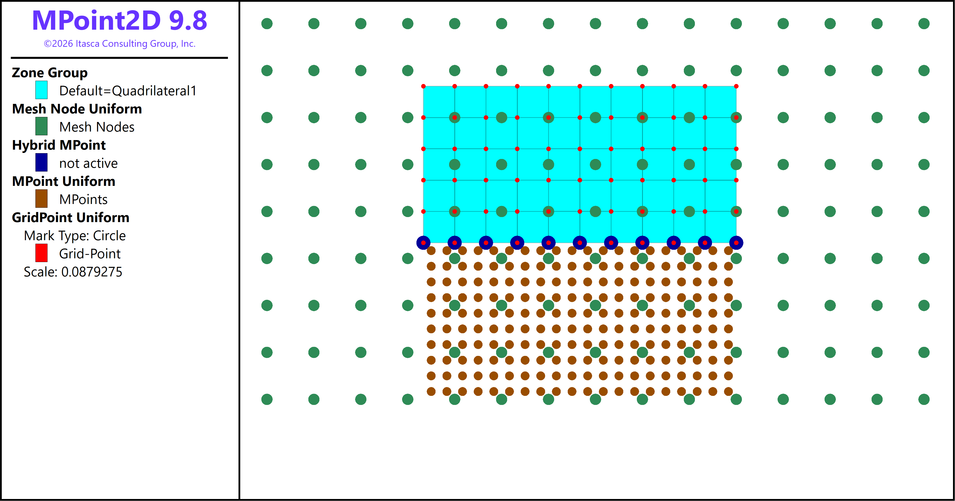
Figure 1: The figure shows a hybrid zone–material-point workflow. The zones are shown in cyan, the material points in brown, the background grid nodes in green, the hybrid points in purple and the grid points in red.
Background grid
The background grid must be defined before material points are generated or
imported. The command mpoint node spacing specifies the background-node
spacing. The model domain must already exist.
model domain extent 0 12 0 6
mpoint node spacing 0.20
In MPoint3D:
model domain extent 0 12 0 1 0 6
mpoint node spacing 0.20
The node spacing should resolve stress gradients, geometry, contact regions, and expected deformation bands. Refining the background grid and increasing the material-point resolution are recommended, when computationally practical, to improve the representation of stress gradients, deformation patterns, contact zones, and localized failure mechanisms. A finer background-grid spacing generally increases spatial accuracy, while a larger material-point resolution reduces under-sampling within each grid cell and can improve the smoothness of the transferred fields. Refinement may also reduce numerical noise and improve solution stability; however, it usually increases computational cost and may require a smaller stable timestep. A mesh-sensitivity study should therefore be performed by comparing the results from progressively refined background grids and material-point distributions until the quantities of interest, such as displacement, stress, reaction force, or runout distance, show sufficiently small changes.
Direct material-point generation
The command mpoint generate creates material points inside a specified
range. The resolution option specifies the number of material points per
background-node spacing in each coordinate direction. The group option
assigns a group to the generated points.
MPoint2D example:
mpoint generate resolution [mp_resolution] group 'Soil' ...
    range position-x 0 [soil_length] ...
          position-y 0 [soil_height]
MPoint3D example:
mpoint generate resolution [mp_resolution] group 'Soil' ...
    range position-x 0 [soil_length] ...
          position-y 0 [soil_width] ...
          position-z 0 [soil_height]
Direct generation is convenient for rectangular or range-defined regions and avoids temporary zones. The constitutive model and properties must be assigned directly to the generated points; see Regions, Constitutive Models, and Properties.
Creation from zones
Zones are useful for complex geometry, imported meshes, stratigraphy, and
initial-stress generation. Create and group the zones, assign the zone
constitutive model and properties, establish the desired zone state, define
the MPoint background grid, and then use mpoint import.
zone create brick ...
zone cmodel assign mohr-coulomb range group 'Soil'
zone property density 2000 young 50e6 poisson 0.3 ...
    friction 30 cohesion 10e3 range group 'Soil'

model domain extent 0 20 0 10
mpoint node spacing 0.25
mpoint import from-zones
By default, mpoint import transfers the zone density, constitutive model,
properties, groups, and supported state variables to the new material points.
The zones are deleted unless the keep option is specified. Confirm the
imported stress convention and pore-pressure state when using coupled models.
Hybrid zone–MPoint workflow
A hybrid workflow retains zones where a Lagrangian mesh remains suitable and
uses material points where large deformation is expected. The command
mpoint hybrid-points identifies coupling locations. The command
mpoint zone-conversion activates automatic conversion of distorted or
selected zones to material points.
; Zone and MPoint boundary conditions are both required.
zone face group 'Coupling' internal range ...
mpoint hybrid-points range group 'Coupling'
mpoint zone-conversion interval 10 radius-ratio 3.5
Use hybrid modeling when only a portion of the model is expected to undergo large motion, such as slope runout, caving, excavation-induced flow, or local penetration. Verify mass transfer, momentum transfer, constitutive state, and boundary continuity at the zone–MPoint interface.
Selecting a workflow
Use direct generation when:
the material region is simple and range-defined;
no zone-derived initial stress state is required;
the model is intended to be entirely MPoint from the start.
Use import from zones when:
the geometry is easier to create or import as zones using Sketch or a dxf file;
initial stresses or pore pressures are established in a zone model;
material models, properties, groups, and state variables should be inherited.
Use a hybrid workflow when:
only part of the model requires large deformation;
an intact far field should remain zoned;
conversion is expected to occur progressively during the analysis.
| Was this helpful? ... | Itasca Software © 2026, Itasca | Updated: Sep 30, 2026 |
