
Axisymmetric Infinite Line Heat Source in an Infinite Medium (FLAC2D)
Note
The project file for this example is available to be viewed/run in FLAC2D. The project’s main data files are shown at the end of this example.
Problem Statement
An infinite line heat source with a constant heat-generating rate is located in an infinite elastic medium with constant thermal properties. A conceptual model is shown in Figure 1. The material properties and initial and boundary conditions are defined as:
Material Properties: |
|
Density (\(\rho\)) |
2178.5 kg/m3 |
Thermal expansion coefficient (\(\alpha_t\)) |
\(5.4 \times 10^{-6}\) 1/K |
Poisson’s ratio (\(\nu\)) |
0.26 |
Shear modulus (\(G\)) |
27.77 GPa |
Specific heat (\(C_p\)) |
879.23 J/kg-K |
Thermal conductivity (\(k\)) |
4.21 W/m-K |
Initial/Boundary Conditions: |
|
Initial stress state |
none |
Initial temperature (\(T_0\)) |
0 K |
Line Heat Source: |
|
Line heat source (\(Q\)) |
1442.3 W/m |
It is assumed that the material properties are temperature-independent, the thermal output of the source is constant (no decay) and the heat line source is of infinite length.
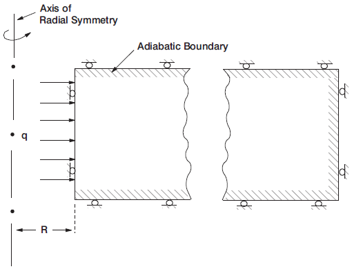
Figure 1: Conceptual axisymmetric model.
Analytical Solution
The analytical solution for this problem is given by Nowacki (1962):
where \(\kappa\) is the thermal diffusivity, defined as \(\kappa = \frac{k}{\rho C_p}\), \(r\) is the radial coordinate, \(t\) is time, and \(m\) is a constant defined as \(m = \frac{1+\nu}{1-\nu}\alpha_t\).
Results
An axisymmetric FLAC2D model is applied to this problem. The line of symmetry is aligned with the line heat source. The heat source is assumed to have a fictitious radius of \(R = 0.01\) m so that the applied flux will be:
The constant heat flux \(q\) is applied to the left boundary, while the rest of the boundaries are kept adiabatic to represent thermal symmetry planes. The right boundary is extended far enough to simulate infinity. The upper and lower sides are mechanically fixed in the vertical direction to represent shear-free symmetry planes. Right and left boundaries are mechanically fixed in the x-direction. The problem is first solved for the thermal response, and then the mechanical response is solved based on the thermal solution. The analytical solutions for ramperature and radial displacment are programmed with FISH functions and stored as tables to allow for comparison to FLAC2D results.
The results of this analysis are summarized:
Figure 2 compares the FLAC2D temperature evolution over 5 years to the analytical solution. The agreementis excellent.
Figure 3 compares the FLAC2D radial displacement at the time of 5 years to the analytical solution. The agreement is fairly good for \(r<100\) m, but the effect of fixed horizontal displacement at \(r=500\) m makes the FLAC2D solution slightly underestimate the analytical displacement, i.e, a bounday condition artifact.
Figure 4 compares the FLAC2D radial stress at the time of 5 years to the analytical solution. The agreement is very good.
Figure 5 compares the FLAC2D hoop stress at the time of 5 years to the analytical solution. The agreement is very good.
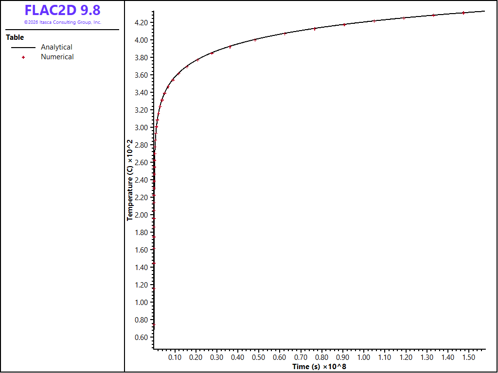
Figure 2: Temperature evolution over 5 years at the heat source boundary.
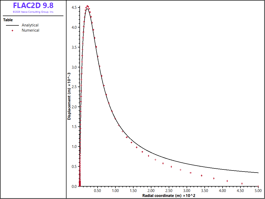
Figure 3: Radial displacement at 5 years.
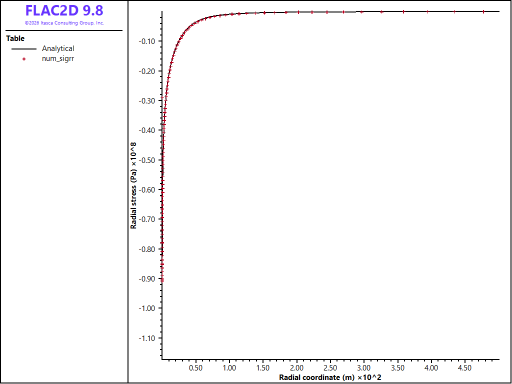
Figure 4: Radial stress at 5 years.
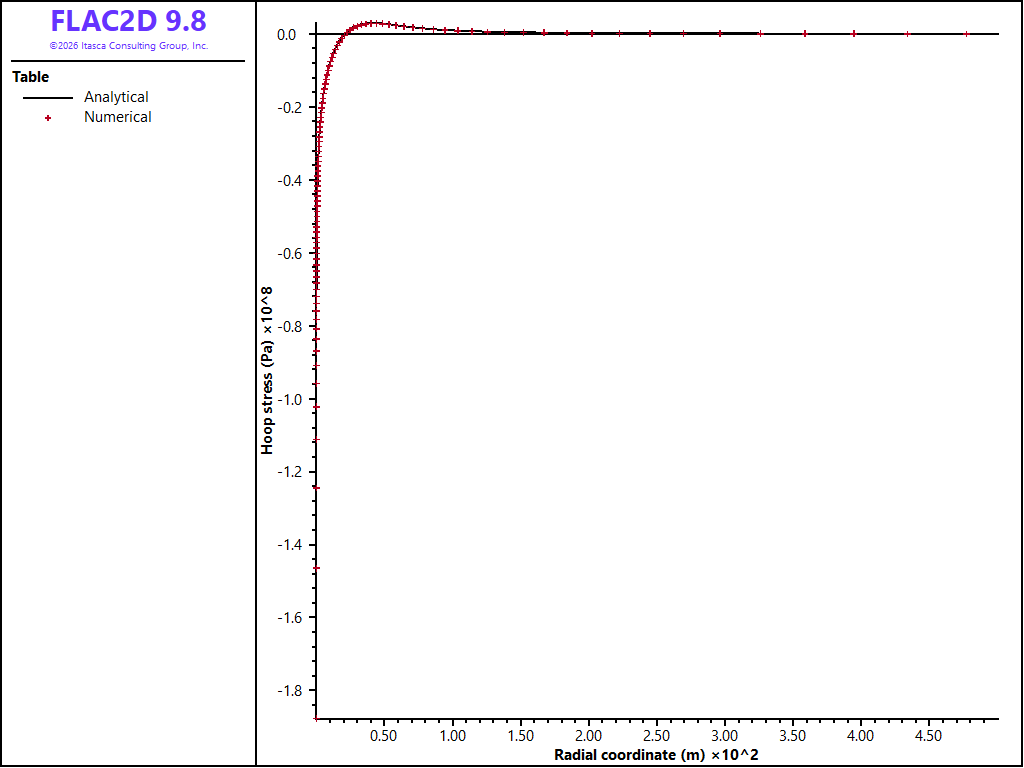
Figure 5: Hoop stress at 5 years.
Reference
Nowacki, W. Thermoelasticity. New York: Addison-Wesley (1962).
Data File
infinitelineheatsource.dat
model new
model configure axisymmetry thermal
model large-strain off

[Q = 1442.3]      ; Heat source (W)
[R = 0.01]        ; Fictious inner radius (m)
[h = 1.0]         ; Height (m)
[k = 4.21]        ; Thermal conductivity (W/(m*K))
[c = 879.23]      ; Heat capacity (J/(kg*K))
[rho = 2178.5]    ; Density (kg/(m^3))

[bulk = 48.6e9]   ; Bulk modulus (Pa)
[shear = 27.77e9] ; Shear modulus (Pa)
[alpha = 5.4e-6]  ; Thermal expansion coeff. (1/K)

[flux = Q / (2*math.pi*R*h)]

zone create quadrilateral point 0 ([R],0) point 1 (500,0) ...
    point 2 ([R],[h]) point 3 (500,[h]) size 100 2 ratio 1.1 1.0
zone face skin

zone cmodel assign elastic
zone property density [rho] bulk [bulk] shear [shear]

zone gridpoint fix velocity-y range group 'Skin=Top'
zone gridpoint fix velocity-y range group 'Skin=Bottom'
zone gridpoint fix velocity-x range group 'Skin=East'
zone gridpoint fix velocity-x range group 'Skin=West'

zone thermal property conductivity [k] ...
    specific-heat [c] expansion [alpha]

zone face apply flux [flux] range group 'Skin=West'

history interval 100
model history name 'time' thermal time-total
zone history name 'temp' temperature position ([R],0.0)

zone thermal implicit on
model solve-thermal time-total [86400*365*5]
model solve-static
⇐ Smooth Circular Footing on an Associated Mohr-Coulomb Material (FLAC2D) | Transient Advection due to Fluid Injection (FLAC2D) ⇒
| Was this helpful? ... | Itasca Software © 2026, Itasca | Updated: Sep 30, 2026 |
