
Examples • Example Applications
Landfill slope with slurry wall (FLAC2D)
Problem Statement
Note
The project file for this example is available to be viewed/run in FLAC2D. [1] The project’s main data file is shown at the end of this example.
This example presents a simplified model using FLAC2D to examine the stabliy of landfill embankment over varved clays. The model was originally created in FLAC 4.0 by Burlingame, Funda and Hart (2006). The model consistes of four layers: on top it’s a wastefill up to 36 meter, under this is a 4.6 meter thick sand and gravel, overlying up to 9.1 meter of varved clay, and then up to 4.6 meter of rock. Material properties are shown in Table 1.
Property |
Waste |
Sand |
Clay |
Rock |
|---|---|---|---|---|
Density (kg/m^3) |
1440 |
2080 |
2020 |
2500 |
Young’s Modulus (MPa) |
8.0 |
130 |
19.2 |
5000 |
Poisson’s ratio |
0.2 |
0.3 |
0.49 |
0.3 |
Cohesion (kPa) |
19.15 |
0 |
25 |
1000 |
Friction (degrees) |
25 |
42 |
0 |
30 |
Tension (kPa) |
0 |
0 |
0 |
10 |
Factor-of-safety results are calculated for three different cases:
Constant undrained shear strength for clay layer
Undrained shear strength for clay layer is a function of vertical effective stresses, and
Adding a slurry wall.
Results are compared at the end.
Modeling Procedure
The modeling procedure is divided into five steps:
Model setup and assign material propeties.
Calculate the static equilibrium state for the site.
Two phreatic surfaces are develolped.
A factor-of-safety calculation is performed.
Undrained shear strenghth for the clay is updated as a function of effective stress and factor-of-safety calculation is performed again.
A slurry wall is added to the model and factor-of-safety calculation is performed.
These steps are described separately in the sections below.
Model Setup and Material Properties
The mesh in this example can be exported from FLAC 8.1(Utility/Extrude) as grid file (f2grid) and then imported to FLAC2D (File/Grid/Import from FLAC2D). Or open FLAC 8.1 GUI, Build/Virtual and press Export button and select Flac2d sketch(Extruder). This will export geometries from the FLAC model builder as Sketch commands that can be read by FLAC2D.
In this example, The model geometry is instead built from scratch in the Sketch workspace. The commands generated by the Sketch operations are given in the included data file sketch.dat.
Select File/New/Sketch set …, create a new sketch with a name (slope). Open the Point/Edge Tools, draw the sketch lines for the landfill slope. The sketch lines should appear as shown in Figure 1
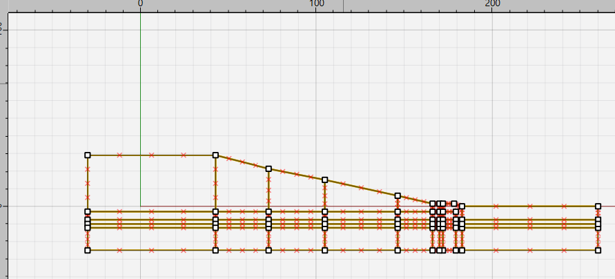
Figure 1: Sketch lines for landfill.
Next, on “Mesh Tools”, use autosize to set zone length to 2.4, as shown in Figure 2
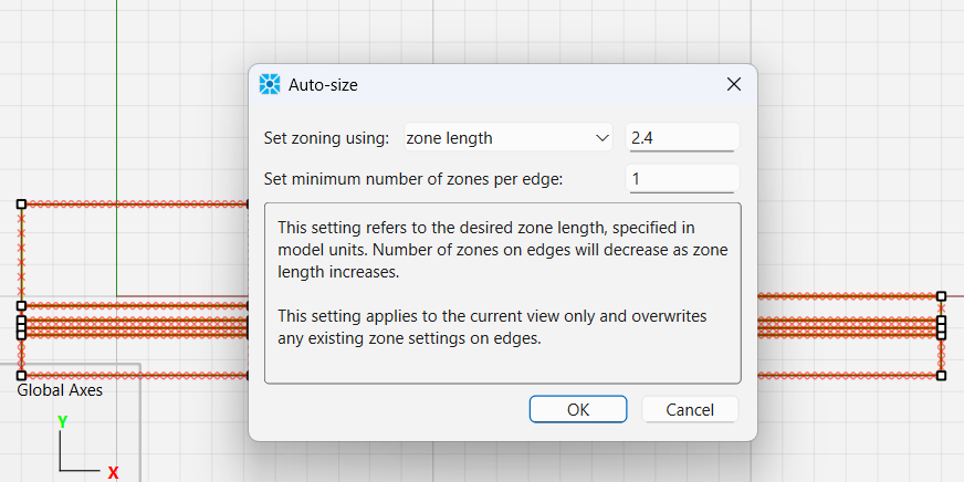
Figure 2: Sketch lines to mesh for landfill.
Press the Mesh All Polygons button.
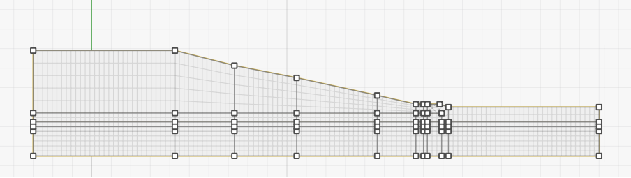
Figure 3: Sketch mesh for landfill.
Next, select blocks and assign group names. The model has 4 layers as shown in Figure 4.
Finally click the button to Create zones and save the model state (sketch.sav). You can also save the commands generated while using Sketch by clicking on the “State Record” tab, right-clicking, and selecting “Save to file as data file”.

Figure 4: Landfill layers with group names.
After you create zones, the Model view will appear in the workspace. To show the layer names, select “Construction” for the group slot being plotted.
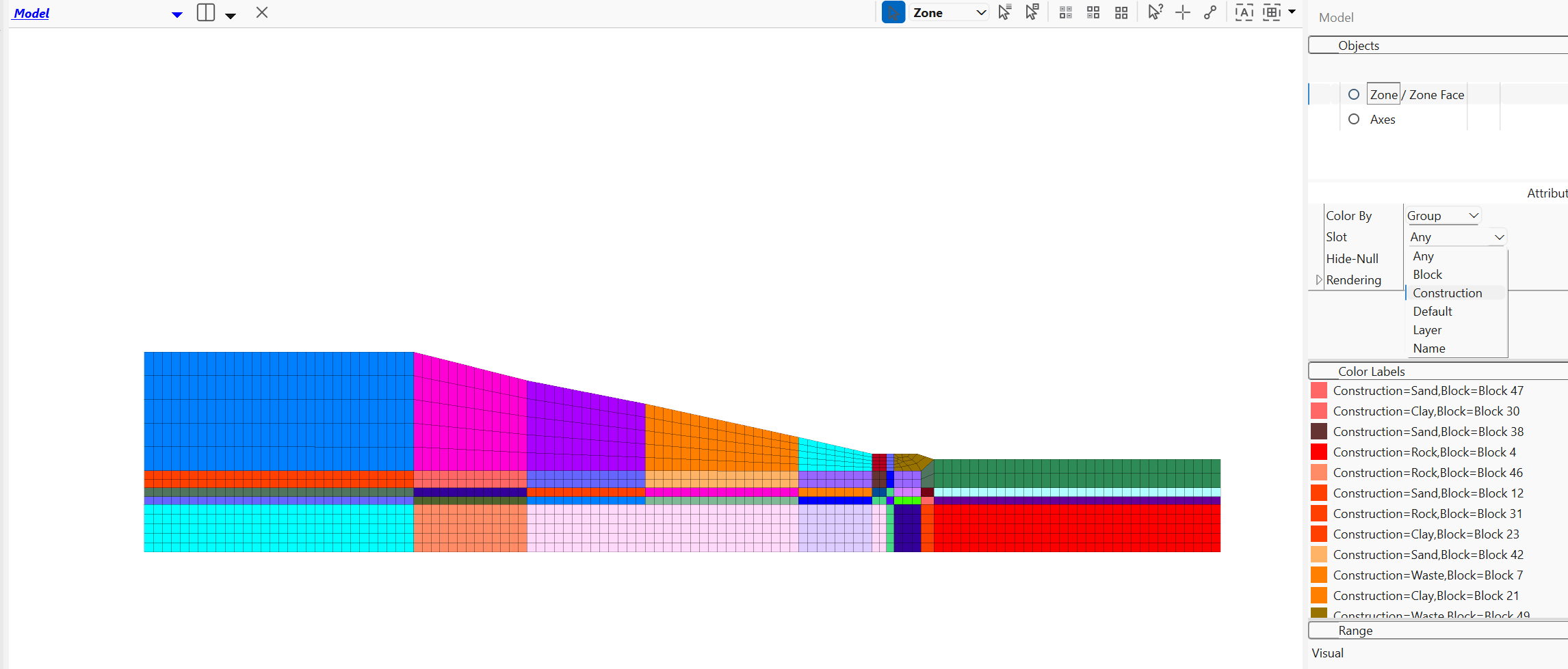
Figure 5: Select the Construction slot for plotting
We need a dense mesh for waste layer. Select the waste layer, and then select Densify the Selected Zones …, to densify the zones 2x2 in x and y directions, as shown below:
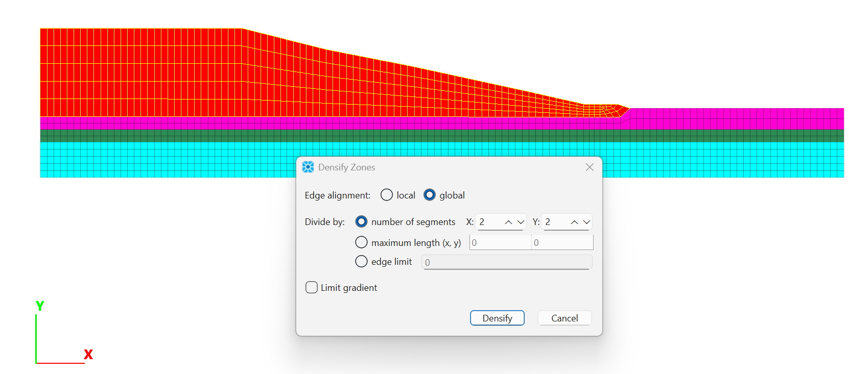
Figure 6: Densify zones in waste layer.
We will use the Model Pane again to assign constitutive models and the material properties. From the Model view in the workspace, Select all of the zones (Ctrl-A) and set the constitutive model to Mohr-Coulomb. Now with the waste layer selected, choose , enter the properties by hand for each property as shown in Figure 7. Repeat for the other 3 layers (properties are shown in Table 1).
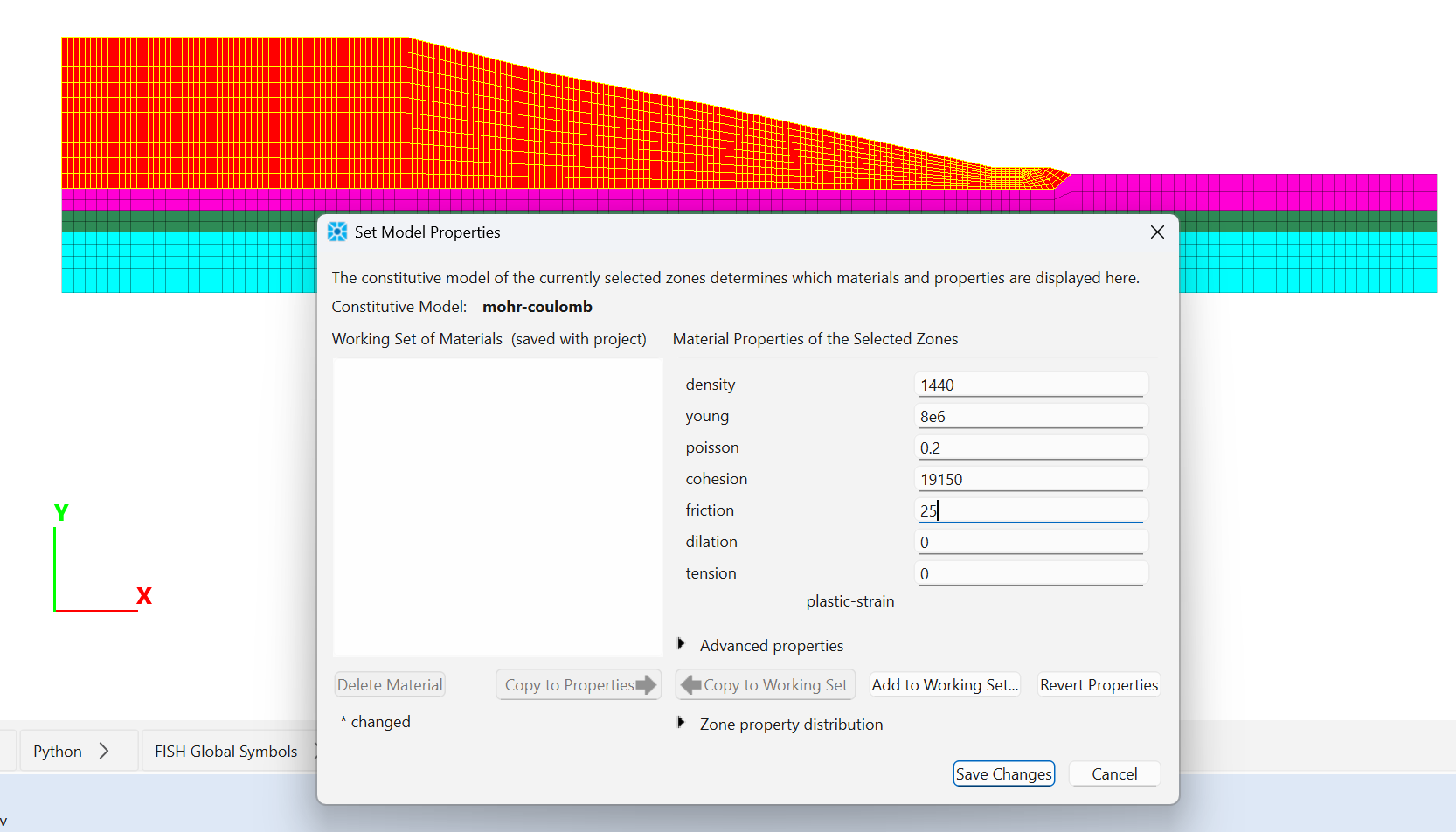
Figure 7: Assign material properties.
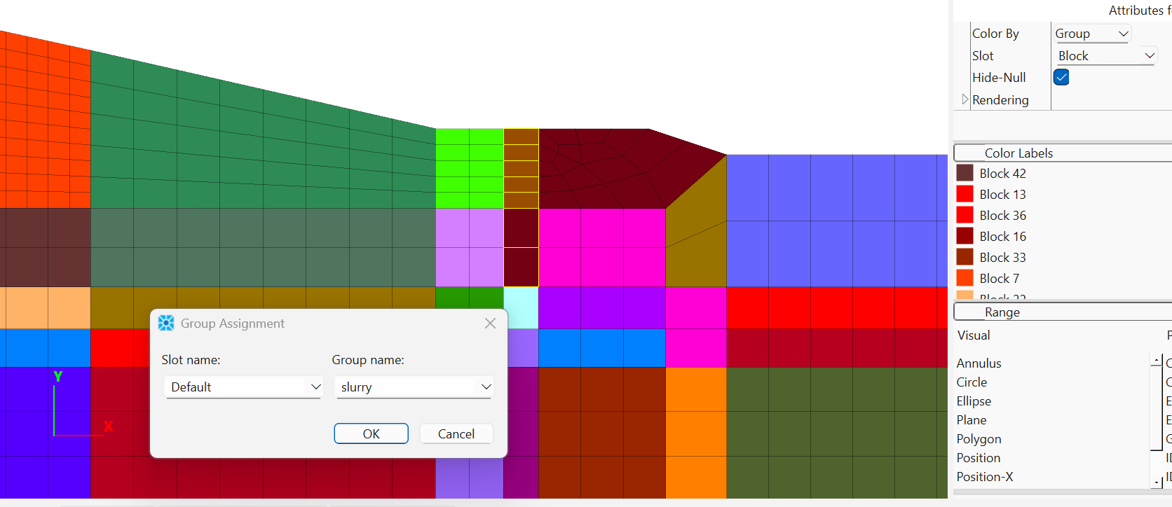
Finally, we can identify zones that make up the slurry wall. Change the group slot to Block. Select block 27 and 28 as shown. Change the group name to “slurry”.
Save the model state and the project.
Establish Initial State of Stress and pore pressure
The data file used to set up boundary conditions, initial conditions, fluid properties, and step to equilibrium is shown in fluid.dat.
This model requires configuring fluid analyis (model configure fluid-flow). The acceleration of gravity is set to 9.81 m/sec2 (positive means acting downward). This model follows the standard boundary conditions: fixed degrees of freedom at the bottom and roller boundaries on the sides. The command zone attach by-face should be used before cycling, to ensure continuous model behavior (the waste layer is densified). An initial equilibrium state is achieved with the model solve-static elastic command.
To perform the fluid flow analysis, the fluid-related material properties: water density, porosity and hydraulic-conductivity are assigned. The water table is located at the top of the clay layer and the pore pressures are initialized by specifying a water head. The datum to use as the origin for purposes of calculated head height is at (0,-25). This can be performed by the following command:
zone gridpoint pore-pressure head 22 datum 0,-25
Next, we need to set up a fluid boundary to develop a perched water table. At left side, the water head is about 19 meters above the low permeability layer, the command zone face apply is used to add the water head at the left side boundary:
zone face apply head 19 range group 'West' position-y 0 19
The steady flow state is performed via the command zone fluid steady-state. The pore pressure distribution is shown in Figure 9:
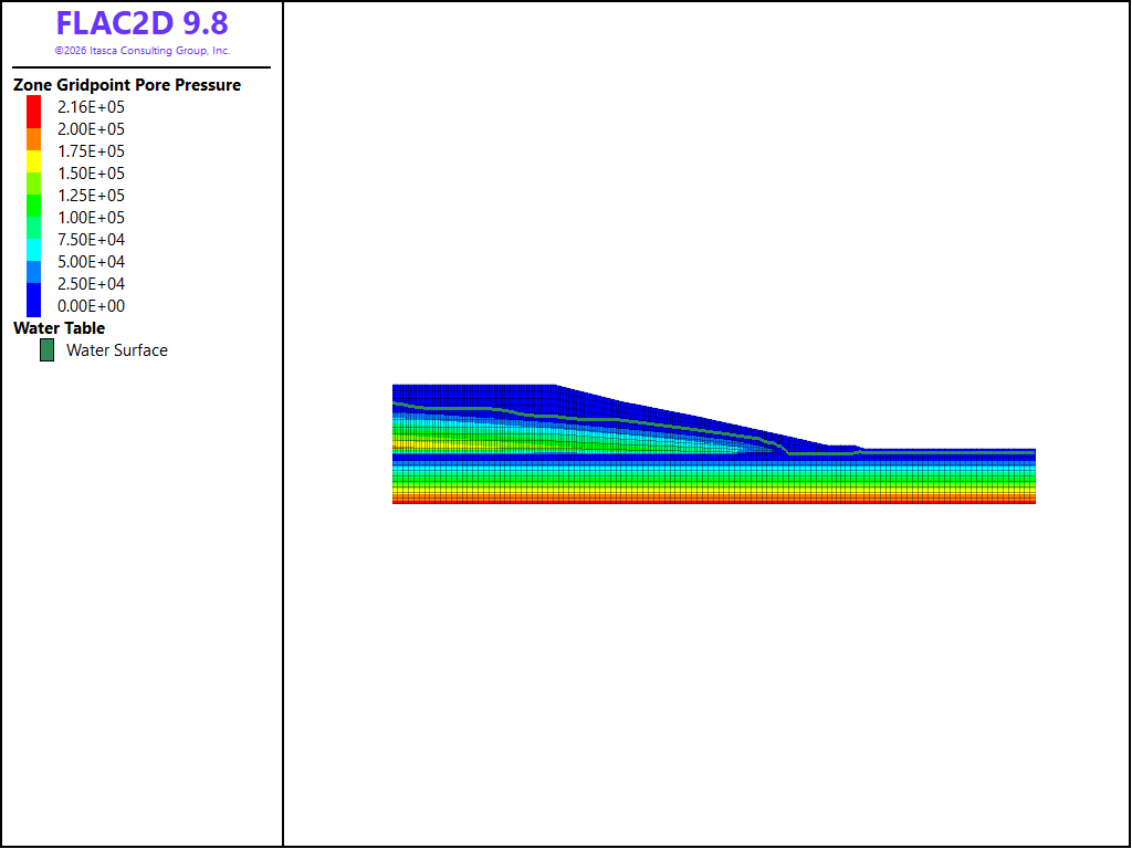
Figure 9: Pore pressure distribution.
The model needs to perform mechanical-only calculations to reach equilbrium after the pore pressures are developed, this is done with the model solve-static command.
Factor of Safety calculations
Before the factor-of-safety runs, the model should be re-initialized to zero displacements and the flow calculation is turned off (model fluid off). The factor-of-safety calculation is performed via command: model factor-of-safety. The landfill does not fail for the input properties, but with a low factor of safety of 1.08, failure along the clay layer is evident (Figure 10).
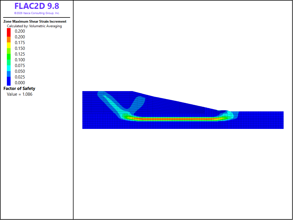
Figure 10: Factor of safety value and maximum shear strain countour for case I.
Next, we update the undrained strength property for the clay as a function of vertical effetive stress. A simple FISH function is adopted here:
; Update clay property using FISH.
fish operator update_prop(z)
    if zone.group(z,'Construction') = 'Clay'
        local effsyy   = zone.stress.effective.yy(z)
        local u_co = -0.16 * effsyy
        zone.prop(z,'cohesion') = u_co
        zone.prop(z,'friction') = 0.0
    endif
end
the model is stepped to an equilibrium state using the command model solve-static. The factor-of-safety calculation is performed again. As shown in Figure 11 the calculated FoS value is increased up to 1.64.
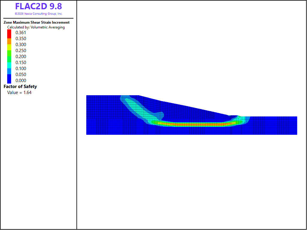
Figure 11: Factor of safety value and maximum shear strain countour for stress-dependent clay properties (case II).
Next, we install slurry wall at toe of the slope using zones. The zones at the slurry wall are excavated and stresses for those zones are set to zeros. This is achieved with the command:
zone null range group "Slurry"
We assign slurry wall properties to the zones at toe of the slope:
;Installing slurry wall
zone cmodel assign mohr-coulomb range group "Slurry"
zone property density=1000.0 young 4.8e+03 poisson 0.3 ...
              cohesion=0.0 friction=10.0 dilation=0.0 tension=0.0 ...
              range group "Slurry"
The factor-of-safety calculation is performed, the calculated FoS value is lowered to 1.35 because of effect of the slurry wall, as shown in Figure 12. Failure develops at toe of the slope, where the slurry wall is installed.
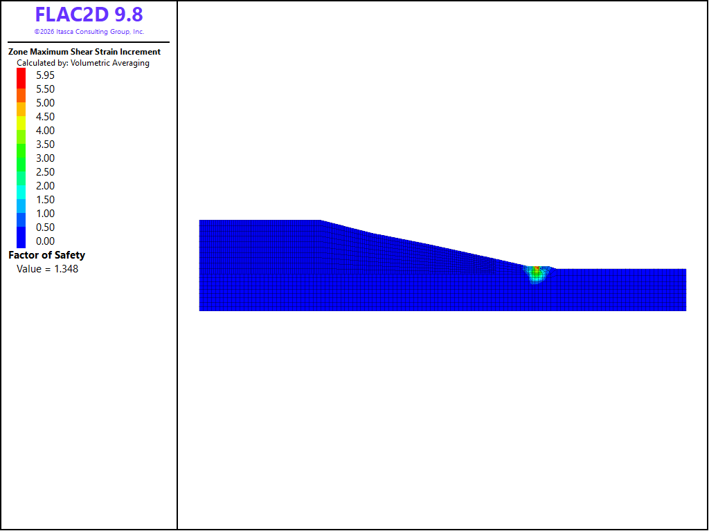
Figure 12: Factor of safety value and maximum shear strain countour with a slurry wall present (case III).
References
- Burlingame M.J, Funda A.M and Hart R.D, Modeling of Landfill Stability with Vertical BarrierWalls: A Practical Example Using Limit Equilibrium and Numerical Methods, in GeoCongress 2006: Geotechnical Engineering in the Information Technology Age
Data Files
model.dat
model restore 'sketch'
zone face skin
zone select true  group "Construction=Waste" and "Block=Block 3" only by zone
zone select true  group "Construction=Waste" and "Block=Block 9" only by zone
zone select true  group "Construction=Waste" and "Block=Block 8" only by zone
zone select true  group "Construction=Waste" and "Block=Block 7" only by zone

zone densify global segments 2,2 range selected
zone select off range use-hidden
zone select
zone cmodel assign mohr-coulomb range selected
zone select off range use-hidden
zone select true  group "Construction=Rock" by zone
zone property density 2500 young 5e+9 poisson 0.3 range selected
zone property cohesion 1e+06 friction 30 tension 10000 range selected
zone select new  group "Construction=Clay" by zone
zone property density 2020 young 1.92e+7 poisson 0.49 range selected
zone property cohesion 25000 range selected
zone select new  group "Construction=Sand" by zone
zone property density 2080 young 1.3e+08 poisson 0.3 range selected
zone property friction 42 range selected
zone select new  group "Construction=Waste" by zone
zone property density 1440 young 8e+06 poisson 0.2 range selected
zone property cohesion 19150 friction 25 range selected
zone select off range use-hidden
zone select true  group "Construction=Waste" and "Block=Block 28" only by zone
zone select true  group "Construction=Sand" and "Block=Block 27" only by zone
zone group "Slurry" slot "Default"  range selected
zone select off range use-hidden
model save 'model'
fluid.dat
mechanical.dat
model restore 'fluid-steady'

; mechanical only.
model solve-static
model save 'mechanical'

; reset displacements
zone gridpoint initialize displacement 0 0

model fluid off
model factor-of-safety filename 'landfill'
mechanical.dat
model restore 'fluid-steady'

; mechanical only.
model solve-static
model save 'mechanical'

; reset displacements
zone gridpoint initialize displacement 0 0

model fluid off
model factor-of-safety filename 'landfill'
updatedprop.dat
model restore 'mechanical'

; Update clay property using FISH.
fish operator update_prop(z)
    if zone.group(z,'Construction') = 'Clay'
        local effsyy   = zone.stress.effective.yy(z)
        local u_co = -0.16 * effsyy
        zone.prop(z,'cohesion') = u_co
        zone.prop(z,'friction') = 0.0
    endif
end
[update_prop(::zone.list)]

model solve-static
model save 'updatedprop'

; reset displacements
zone gridpoint initialize displacement 0 0

model fluid off
model factor-of-safety filename 'landfill2'
slurrywall.dat
model restore 'updatedprop'

;the stresses in the zones are initialized to zero
zone null range group "Slurry"

;Installing slurry wall
zone cmodel assign mohr-coulomb range group "Slurry"
zone property density=1000.0 young 4.8e+03 poisson 0.3 ...
              cohesion=0.0 friction=10.0 dilation=0.0 tension=0.0 ...
              range group "Slurry"

model save 'slurrywall'

zone gridpoint initialize displacement 0 0

model fluid off
model factor-of-safety filename 'landfill3'
Endnote
⇐ A Roadway Embankment with Surcharge Loads and Reinforcement (FLAC2D) | Undrained Cylindrical Cavity Expansion in a Cam-Clay Medium (FLAC3D) ⇒
| Was this helpful? ... | Itasca Software © 2026, Itasca | Updated: Sep 30, 2026 |
