Selecting Nodes
The “Select” tool works with node-related plots displayed in the View Pane. Node-related plots include 2-D and 3-D contour plots, found in the “Control Panel” on the “List” tab under the “Node” plot items group. To select nodes, the node plot item must be the first active plot item in the “Plot Item” pane. Select nodes using these methods:
Click the “Select” tool, then click nodes in the View Pane. Right-click to deselect individual nodes.
Click the “Select” tool, then click and drag to select nodes in a rectangle. Right-click to deselect.
After selecting nodes, press \(Enter\) to open the “Assign Properties for Nodes” dialog shown in The “Assign Properties for Nodes” dialog box.
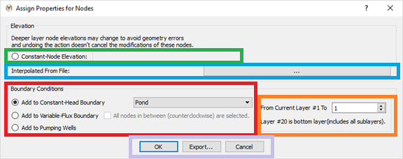
Figure 1: The “Assign Properties for Nodes” dialog box
Several operations can be performed on the selected nodes.
Assign boundary conditions (constant head, variable flux, or pumping wells) shown in Assign boundary conditions to selected nodes. After selecting an option, specify the number of layers for the boundary conditions.
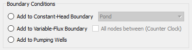
Figure 2: Assign boundary conditions to selected nodes
Change the elevation of the selected nodes, as shown in Assign constant elevation to selected nodes
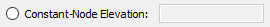
Figure 3: Assign constant elevation to selected nodes
Interpolate selected node elevations using a data file by clicking the button next to “Interpolated from File” shown in Assign elevation by interpolating elevation data. The data file format is x, y, z space-delimited values.

Figure 4: Assign elevation by interpolating elevation data
After selecting a boundary condition shown in
fig-assign-boundary-conditions, specify the number of layers. To select nodes in multiple layers, specify which layers to modify (seefig-multiple-layers-specification).
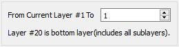
Figure 5: The multiple layers specification dialog box
Export the data. Export selected node numbers to a .DAT file using the export button shown in
fig-export-options-nodes-elements. The output file contains selected node numbers and corresponding elevations.
Figure 6: The options available for both nodes and elements
To exit “Select” mode, click the “View Mode” tool after closing the “Assign Properties for Nodes” dialog. To deselect all selected elements before editing, press kbd:\(Esc\).
| Was this helpful? ... | Itasca Software © 2026, Itasca | Updated: Jun 10, 2026 |
