Selecting Elements
MINEDW provides several tools for selecting nodes and elements. Selection is essential when performing these tasks:
Assigning and editing element properties (e.g., hydraulic conductivity, storage zones, recharge zones, evaporation zones).
Assigning and editing node-related boundary conditions (e.g., constant heads, pumping wells, variable-flux boundaries).
Moving nodes within the finite-element mesh.
Adding pinch-outs for improved vertical discretization.
Refining and extending the mesh.
Selecting Elements in 2-D
When an element-based plot is displayed, you can select elements using these methods:
Click Selection: Use the Select tool to click individual elements in the View Pane. - Right-click to deselect an element. - Press Esc to clear all selections.
Rectangle Selection: Click the Select tool, then click and drag to define a rectangle. - Right-click and drag a rectangle around selected elements to deselect them.
Polygon Selection: Click the Select tool, then click the Select with Polygon tool (see Mouse Tools). - Draw a polygon around the desired area and press Enter to close it.
After selecting elements, press Enter to open one of these dialog boxes:
These dialogs edit recharge zones, evaporation zones, or geological zones.
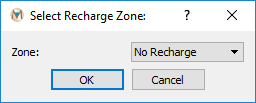
Figure 1: Select Recharge Zone dialog box
Recharge Zones To edit recharge zones: 1. Use a 2-D Plane plot item. 2. Change Color By to Recharge. 3. Select elements, then press Enter. 4. In the Select Recharge Zone dialog, assign a zone from the drop-down list.
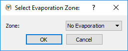
Figure 2: Select Evaporation Zone dialog box
Evaporation Zones The process is similar to recharge zones: 1. Change Color By to Evaporation in a 2-D Plane plot. 2. Select elements, press Enter, and assign a zone from the dialog. For details, see Boundary Conditions.
Geological Zones Use a 2-D Element or 3-D Element plot item to assign geological properties. - Select elements, press Enter, and the Select Geological Zone dialog opens (Select Geological Zone dialog box). - To apply changes across multiple layers, specify the target layer in the attribute panel (Select Geological Zone dialog box with multiple-layer option).
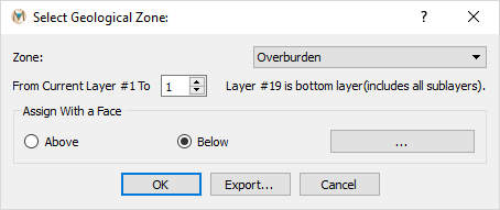
Figure 3: Select Geological Zone dialog box

Figure 4: Select Geological Zone dialog box with multiple-layer option
Exporting Selections Export selected element numbers using the Export function in the Select Geological Zone dialog. The output file lists selected element IDs.
Selecting Elements in 3-D
Elements and zone properties can also be assigned using a 3-D .DXF file.
Add a DXF plot item to the View Pane:
Select List → File Data → DXF.
In the Attributes tab, expand File and choose the DXF file.
If the DXF contains multiple units:
Open the Layers dialog (Attributes dialog box).
Enable only the desired unit before assignment.
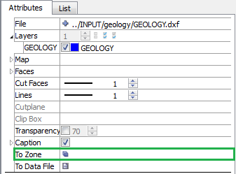
Figure 5: Attributes dialog box
Assign zones:
Click the symbol next to To Zone to open the DXF to Zone dialog (DXF to Zone dialog box).
Select the desired zone from the drop-down.
Choose Volume (for 3-D geologic units) or Face (for structures like faults).
Selection modes:
Whole → selects only elements fully inside the DXF object.
Center → selects elements if their centers are inside the DXF object.
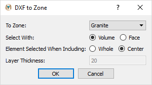
Figure 6: DXF to Zone dialog box
Exiting Selection Mode
To exit Select mode, click the View Mode button.
To deselect all elements, press Esc.
| Was this helpful? ... | Itasca Software © 2026, Itasca | Updated: Jun 10, 2026 |
