Creating a Mesh
Prerequisites
For mesh creation, Rhino must be installed. After installation:
Copy the
MMesh.ghaandtriangulation.dllfiles from the MINEDWbindirectoryPlace these files in:
C:\Users\[YOUR USER NAME]\Application
Data\Grasshopper\Libraries
Open Rhino and import or create features to include in your mesh using Rhino drawing tools or by importing AutoCAD .DXF files. Launch Grasshopper by typing “Grasshopper” into the Rhino command line, or double-click the “Launch Grasshopper” tool icon to open the Grasshopper window.
From the Grasshopper window, open the “template.gh” file in the “bin” directory of the MINEDW installation. A workflow will appear on the Grasshopper canvas designed to create a 2-D mesh for mining-related groundwater flow models. The workflow may be modified using Rhino and Grasshopper tools to suit specific requirements.
Rhino and Grasshopper are external visualization and mesh-generation tools not developed by Itasca. Users should read the Rhino and Grasshopper manuals to become familiar with these tools.
Users should work through tutorials for mesh
generation using Rhino and Grasshopper. The Grasshopper mesh generator
template is shown in fig-grasshopper-template.
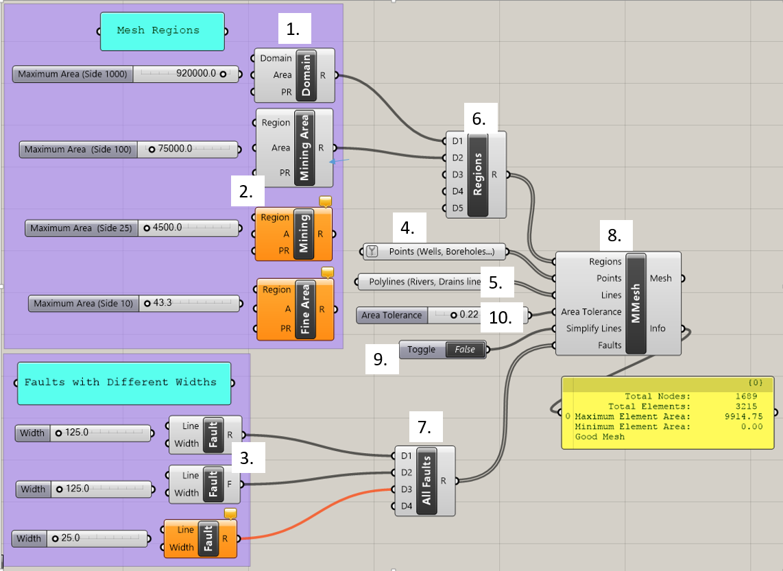
Figure 1: The Grasshopper mesh generator template
The blocks shown in fig-grasshopper-template are called
components. Key components are labeled by number and
explained in The Mesh Components. Components have input
parameters on their left side and output parameters on their right side.
A component box is orange in color if it has a warning message. The
message can be viewed in the comment box on top of the component. The
user assigns features such as rivers, wells, and faults to components in
Grasshopper to add features to the mesh. The grey “All Faults” and
“Regions” (6 & 7) components are used to combine multiple inputs of
the same type. Grey slider blocks, when connected to
input parameters, allow adjustment of parameters like
maximum element area and fault width. The “MMesh” (8) component
creates a mesh that incorporates all the components it is connected to.
The yellow box below the “MMesh” component gives information about the
mesh, including the number of vertices and elements and the minimum
element size once it is created. Components may be connected by clicking
on the half circle next to an input parameter and dragging the mouse to
the half circle next to an output parameter. Components may be
disconnected by right-clicking on a parameter at either end of the
connection and choosing the “Disconnect” option. Once the components
have been connected and assigned with the proper construction features,
the mesh can be viewed and will dynamically update as changes are made
to various components. The components and the steps involved in making a
mesh are discussed in detail in the following sections.
| Was this helpful? ... | Itasca Software © 2026, Itasca | Updated: Jun 10, 2026 |
