MPoint Modeling • Examples
Creating Material Points From Zones
The project file for this example may be viewed/run in MPoint3D.[1] The main data file used is shown at the end of this example.
This example demonstrates how mpoints can be imported from zones using the mpoint import from-zones command. This can be used to convert an existing FLAC model to a MPoint model. However, it is also the preferred method for creating a new MPoint model from scratch.
Three sections are presented: (1) setting the number of mpoints per zone to import, (2) densifying the zone grid before importing mpoints, and (3) setting the mpoint properties/attributes.
The Number of MPoints
The data file “import_number.dat” in this example creates a very simple pyramid shape. The lower three layers consist of hexahedral zones, and the upper layer of pyramid-shaped zones (see Figure 1).
model new
model large-strain off
; create zones
zone create pyramid point 0 0 0 0 ...
                 point 1 1 0 0 ...
                 point 2 0 1 0 ...
                 point 3 0.5 0.5 0.5 ...
                 size 4 4 4
To create mpoints, one must first create a domain and a background mesh. Subsequently the mpoints can be imported from the zones. The default behavior for the mpoint import from-zones command is to delete the zones after importation. However, for illustrative purposes, the zones are kept using the keep keyword.
; import mpoints
model domain extent 0 1
; background mesh must be specified before importing mpoints
mpoint node spacing 0.5
; set the number to 1, 2, 3 or 4
mpoint import from-zones number 1 keep
Varying the number from 1 to 4 is shown in Figure 1 to Figure 4. For hexahedral zones, the number is directly related to the number of mpoints per direction (zone local direction). For triangular (tetrahedral and pyramid) zones, a single mpoint is created when number = 1, and 4 or 5 mpoints when number = 2 (one mpoint per gridpoint for tetrahedra and pyramids respectively). Setting number = 3, creates 5 or 6 mpoints - one per gridpoint plus an additional mpoint at the zone centroid, respectively. Setting number = 4 behaves identical to number = 3 for triangular zones.

Figure 1: MPoints imported from zones with number = 1.

Figure 2: MPoints imported from zones with number = 2.

Figure 3: MPoints imported from zones with number = 3.

Figure 4: MPoints imported from zones with number = 4.
Densifying the Zone Grid
An alternative method to manipulate the number of mpoints in the model is to first alter the zone grid before mpoints are imported. For example, the zone densify command can be used, as in the “import_densify.dat” data file.
In this case, the zones shown in Figure 1 are subdivided, resulting in a larger number of zones as shown in Figure 5. Then again, a number of mpoint can be imported per zone as illustrated above. In this case, a single mpoint was imported per zone for illustration. See the zone densify command for more options on how to densify 2D and 3D grids before importing mpoints.
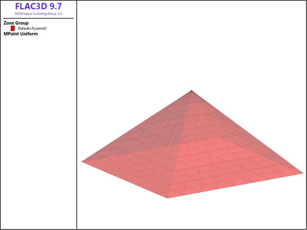
Figure 5: MPoints imported from densified zones with number = 1.
Assigning MPoint Properties/Attributes
When imported, the mpoint volume is always set to the zone volume divided by the number of mpoints created per zone. By default the mpoint density and constitutive model (with all of its property values) are are inherited from the zone. The mpoint displacement, velocity and stress are based on the optional keywords given and the zone type.
The data file “import-interpolate.dat” demonstrates this behavior. Two identical pyramids are created using zones, as shown in Figure 6.
The lower face of the pyramids is fixed, and the zones of each assigned to either a lower or upper group. The zone properties are set per group, with a difference in the Young’s modulus. The model is solved in small strain mode to generate displacements, velocities, and stress.
A domain is created, the background mesh spacing is specified and mpoints are imported from the zones in the upper pyramid. The number of mpoints per zone is set to number = 2, and omitting the interpolate keyword, produces the displacement magnitude and the vertical stress fields as shown in Figure 6 and Figure 7 respectively.
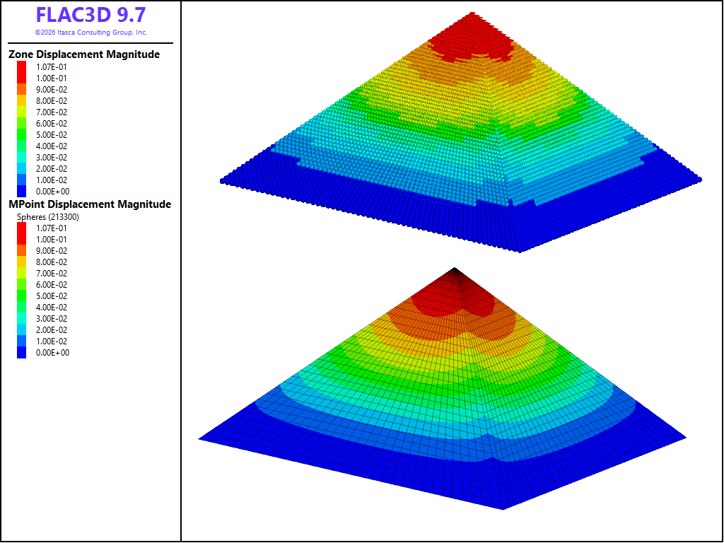
Figure 6: The displacement magnitude of imported mpoints (top) compared to that of zones (bottom) - no interpolation.
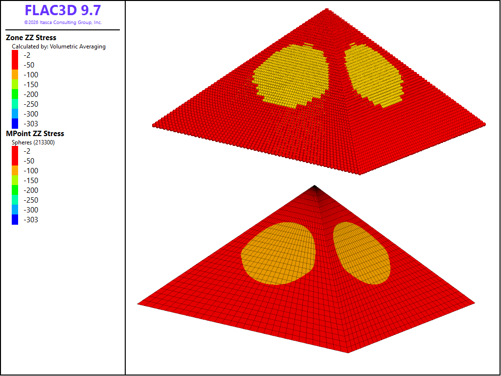
Figure 7: The vertical stress component of imported mpoints (top) compared to that of zones (bottom) - no interpolation.
Note
In Figure 7, the zone stress is not averaged and shown as constant for comparison purposes since the mpoint stress (and all other properties) is not averaged and plotted per mpoint.
It can be seen that the displacement and stress fields of the mpoints are in general in good agreement with that of the zones. Using the interpolate keyword, results in the displacement and stress fields shown in Figure 8 and Figure 9 respectively.

Figure 8: The displacement magnitude of imported mpoints (top) compared to that of zones (bottom) - with interpolation.
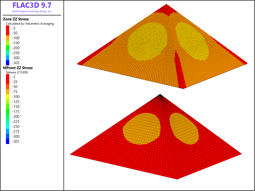
Figure 9: The vertical stress component of imported mpoints (top) compared to that of zones (bottom) - with interpolation.
Note
In Figure 9, the zone stress is averaged, and although the mpoint stress is interpolated from the gridpoints, the plotting is not averaged and shown per mpoint.
Comparing Figure 8 and Figure 9 to Figure 6 and Figure 7, it can be seen that the interpolation results in a smoother displacement and stress field. Lastly, the resolution is increased by setting the zone size = 50 50 50, and the mpoint import number = 4, together with the interpolate keyword, to produce the stress fields in Figure 10 (the zone stress is averaged in the plot)..
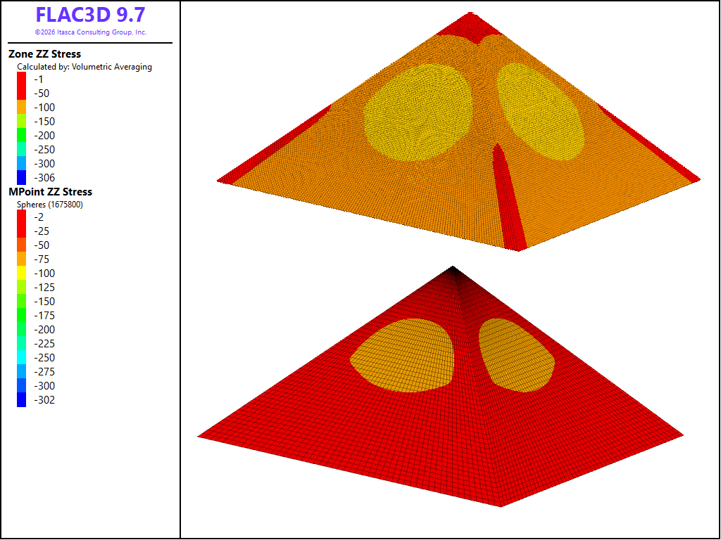
Figure 10: The vertical stress component of imported mpoints (top) compared to that of zones (bottom) - with interpolation and a fine resolution.
Data Files
import_number.dat
model new
model large-strain off
; create zones
zone create pyramid point 0 0 0 0 ...
                 point 1 1 0 0 ...
                 point 2 0 1 0 ...
                 point 3 0.5 0.5 0.5 ...
                 size 4 4 4
; import mpoints
model domain extent 0 1
; background mesh must be specified before importing mpoints
mpoint node spacing 0.5
; set the number to 1, 2, 3 or 4
mpoint import from-zones number 1 keep
import_densify.dat
model new
model large-strain off
; create zones
zone create pyramid point 0 0 0 0 ...
                 point 1 1 0 0 ...
                 point 2 0 1 0 ...
                 point 3 0.5 0.5 0.5 ...
                 size 4 4 4
; densify the zones
zone densify
; import mpoints
model domain extent 0 1
; background mesh must be specified before importing mpoints
mpoint node spacing 0.5
; set the number to 1, 2, 3 or 4
mpoint import from-zones number 1 keep
import_interpolate.dat
model new
model large-strain off
; create zones
zone create pyramid point 0 0 0 0 ...
                 point 1 1 0 0 ...
                 point 2 0 1 0 ...
                 point 3 0.5 0.5 0.5 ...
                 size 30 30 30
[dz = 0.75]
zone create pyramid point 0 0 0 [0+dz] ...
                 point 1 1 0 [0+dz] ...
                 point 2 0 1 [0+dz] ...
                 point 3 0.5 0.5 [0.5+dz] ...
                 size 30 30 30
; zone fixities
zone gridpoint fix velocity range position-z 0 union position-z [dz]
; zone groups
zone group 'lower' range position-z 0 0.25 union position-z [0+dz] [0.25+dz]
zone group 'upper' range position-z 0.25 0.5 union position-z [0.25+dz] [0.5+dz]
; zone properties
zone cmodel assign elastic
zone property young 500.0 poisson 0.2 density 100.0 range group 'lower'
zone property young 1000.0 poisson 0.2 density 100.0 range group 'upper'
; solve the model
model gravity 9.81
model solve
; import mpoints
model domain extent 0 2.5
; background mesh must be specified before importing mpoints
mpoint node spacing 0.5
; import mpoints - select option below
mpoint import from-zones number 2 range position-z [dz] [dz*10]
;mpoint import from-zones number 2 interpolate range position-z [dz] [dz*10]
Endnote
| Was this helpful? ... | Itasca Software © 2026, Itasca | Updated: Jun 10, 2026 |
