
MPoint Modeling • Tutorials
Tutorial: Quick Start (MPoint)
This tutorial steps through the actions necessary to quickly create and run an MPoint model. This is aimed at users familar with FLAC3D and the user interface. The focus is on providing basic familiarity with MPoint and the model components.
Create a new model and a plot that displays zones, the background mesh (referred to as mpoint nodes), and material points (referred to as mpoints). Create a new data file and add the command to set the gravitational acceleration (model gravity) and switch on large strain mode so that the position of mpoints is updated (see Large Strain/Small Strain). MPoints can only be created inside the model domain, which is created using the model domain command.
model new
; Model settings
model gravity 9.81
model large-strain on
model domain extent (-5 5) (-5 5) (0 2.5)
The next steps are to create zones in the form a rectangular column using the zone create command, assign the elastic constitutive model to the zones using the zone cmodel command, initialize the density using the zone initialize command , set the constitutive model properties using the zone property command, and initialize the zone stress using the zone initialize-stresses command. Note that constitutive models must be assigned first,
before properties can be specified for the model(s) assigned.
; Create zones and assign constitutive model
zone create brick point 0 (-1,-1,0) ...
                  point 1 (1,-1,0) ...
                  point 2 (-1,1,0,) ...
                  point 3 (-1,-1,2) ...
                  size 10 10 10
zone cmodel assign mohr-coulomb
; Set zone properties
zone property density 1500 young 100e6 poisson 0.25 ...
  friction 35 cohesion 500 tension 500
; Initialize stress
zone initialize-stresses
Initializing the stress results in the following \(zz\)-stress:
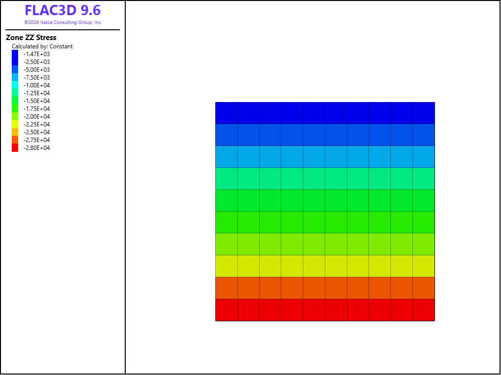
Figure 1: Zones created and the stress initialized.
Next, the background mesh is created using the mpoint node spacing command.
; Create background mesh with 2 mpoints per node spacing
mpoint node spacing 0.2
Viewing the model in the \(x\)-direction, for example, and adding the nodes to the plot, the zones are shown relative to the nodes. Ideally, the node spacing is similar to the zone edge length.
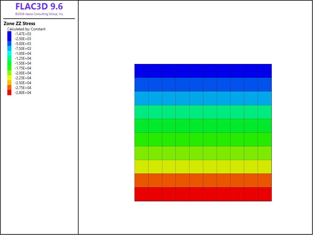
Figure 2: The background mesh shown in relation to the zones.
The mpoints are imported from the zones with the mpoint import command. The mpoint positions and volumes are automatically computed. Additionally the mpoint constitutive models, densities, displacements, group(s), stresses and velocities are inherited from the zones and the zones are deleted.
; Import mpoints from zones and delete zones
mpoint import from-zones
Plotting the mpoint stress in the z-direction, the result is similar to that of the zones before importation.
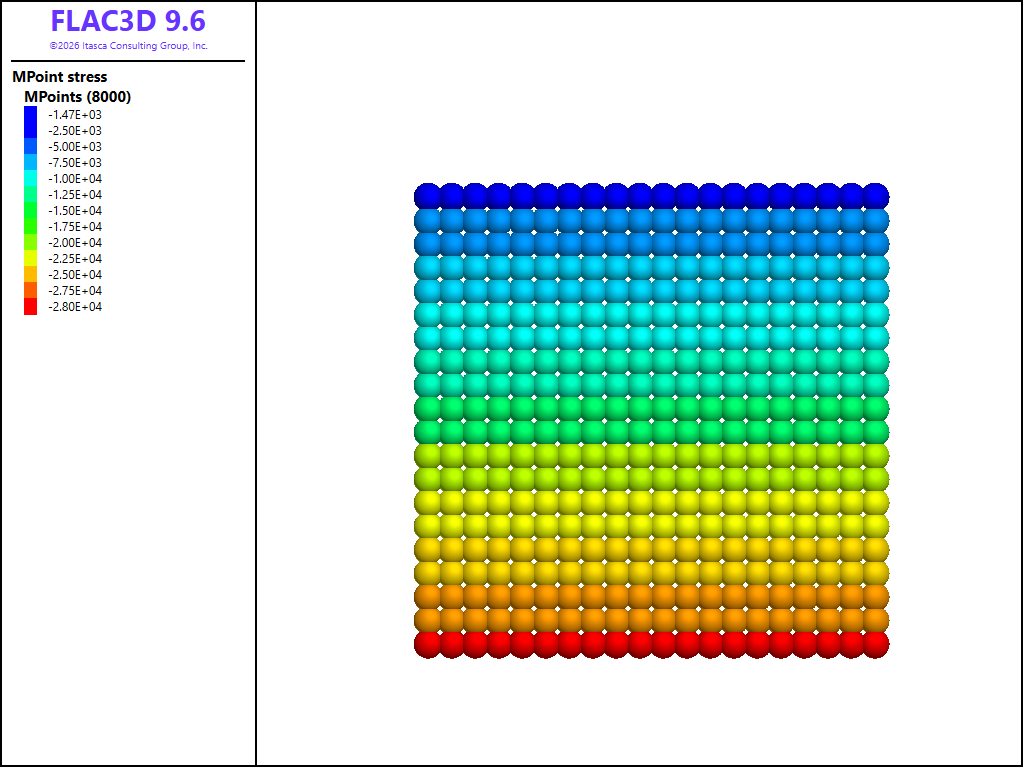
Figure 3: The imported material points with the stress equal to that of the zones.
Constraints are applied to the nodes, by fixing the velocity for all the nodes with a position \(z = 0\).
; Fixities
mpoint node fix velocity range position-z 0
As with FLAC, the default mode of computation uses density scaling for mpoint nodes. In order for the response to be dynamic, the dynamic process must be configured (model configure) as well as the dynamic node damping (mpoint node dynamic).
; Use dynamic mode so that the timestep is computed automatically
model configure dynamic
; Set combined damping for dynamic computations
mpoint node dynamic damping combined 0.7
Next, the model is solved to a specified average ratio.
; Solving the model
model solve ratio-average 2e-2
The final configuration showing the mpoint displacement is then as follow.
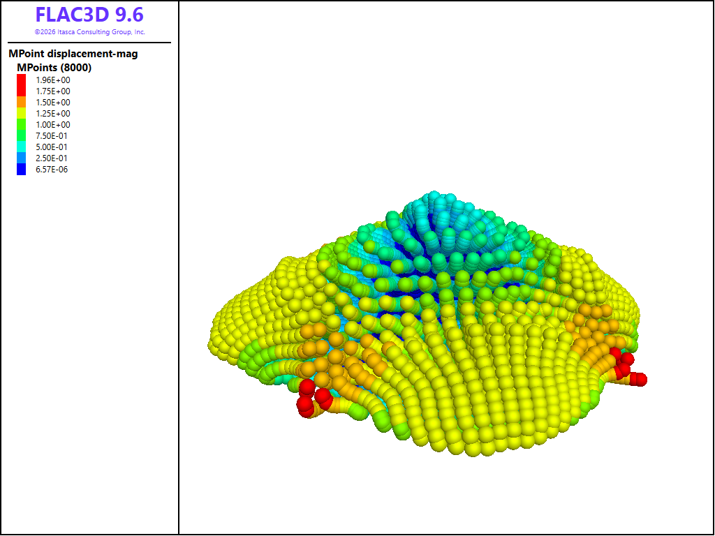
Figure 4: The material points at the end of the simulation.
| Was this helpful? ... | Itasca Software © 2026, Itasca | Updated: Apr 15, 2026 |
