Multistage Tunnel Excavation and Support (FLAC3D)
This project is the 3D counterpart to the 2D Multistage Tunnel Excavation and Support. The project file for this example may be viewed/run in FLAC3D.[1] The main data files used are shown at the end of this example.
Problem Statement
Construction of large railroad, subway, and road tunnels often involves multiple stages of excavation and support, particularly if the tunnels are located at shallow depth and/or in weak ground. A typical example for construction conditions and sequence of a shallow tunnel is illustrated in Figure 1.
In this example, the right half of the tunnel is modeled with a vertical symmetry plane through the tunnel axis. The construction sequence is divided into three major excavation stages:
Stage I: right-side excavation;
Stage II: top-heading excavation; and
Stage III: bench excavation.
Each excavation stage is accomplished in three construction steps:
Step a: initial excavation;
Step b: installation of rockbolt support; and
Step c: installation of a shotcrete lining.
The three steps occur at different times during the advancement of the tunnel face. The stress and displacement fields in the vicinity of a tunnel construction change in the direction of the advancing tunnel face, and this is most rigorously analyzed using FLAC3D. An important issue in the design of supports is the amount of change in the tunnel load that takes place due to the tunnel advancement before the support is installed. The 2D Multistage Tunnel Excavation and Support example utilizes a ground reaction curve to transfer the load to the support. In FLAC2D, this is accomplished by decreasing the elastic moduli of the tunnel core, bringing the model to equilibrium, installing the support, and finally removing the core. In this example, the transfer of load to the supports is captured by the three-dimensional model that explicitly advances the tunel face a specified distance, taken as 1 m for each excavation stage.
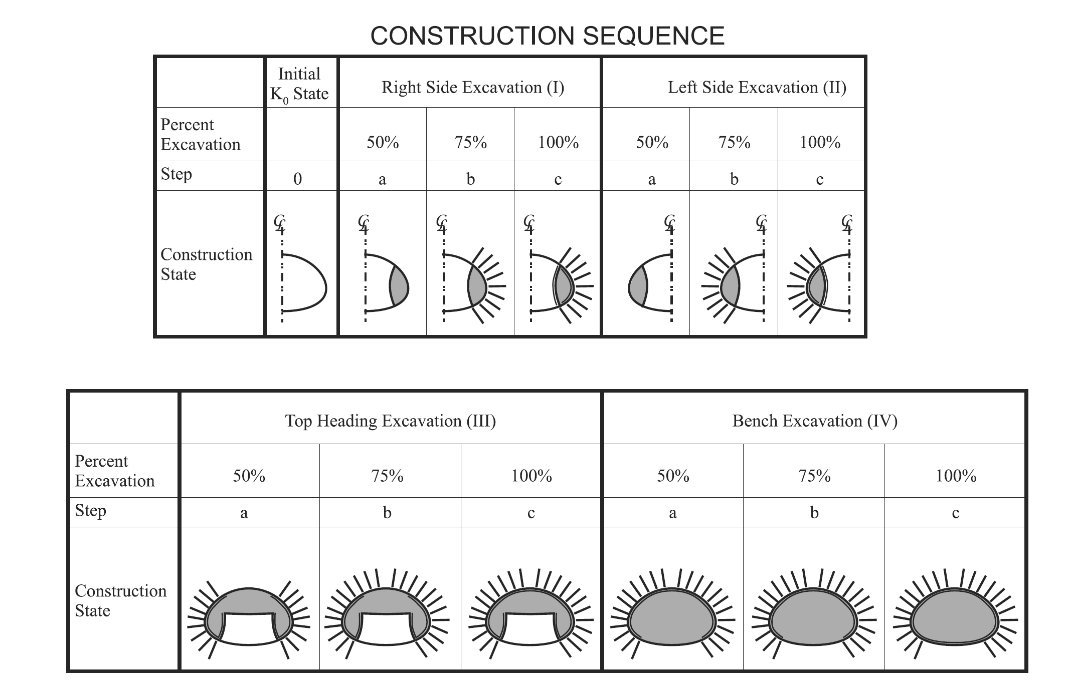
Figure 1: Construction sequence for a multistage tunnel excavation and support.
Model Setup
The tunnel geometry and other construction conditions are shown in Figure 2.
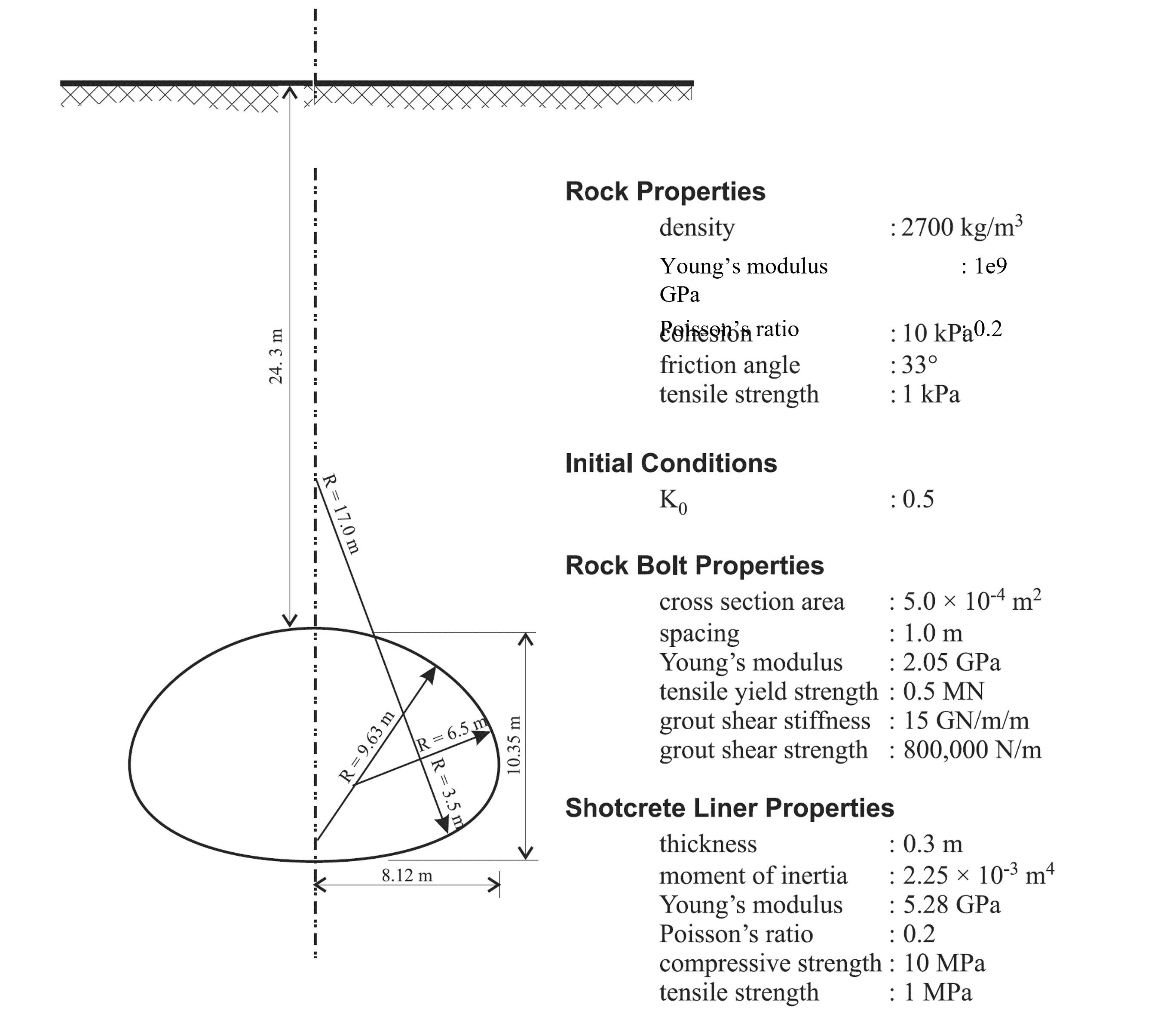
Figure 2: Construction sequence for a multistage tunnel excavation and support.
The mesh is built in Sketch. The tunnel stage groups and face groups are also assigned in Sketch. The model geometry and stage groups are shown in Figure 3.
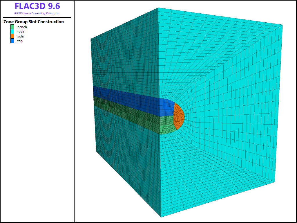
Figure 3: Model geometry and construction stage groups.
Construction Simulation
The first step of construction involves excavation to advance a portion of the tunnel face 1 m (side, top, or bench). No supports are installed during this step and the model is brought to equilibrium. At this state, the cable elements are installed with an offest of 0.5 m from the excavated face, representing the rockbolt support (pile structural elements more accurately model rockbolts, but these require more input parameters and the difference in results in this case is negligible). The locations of the rockbolts are defined by a Sketch set of the rockbolt pattern and the elements are created with the command structure cable import from-sketch. Alternatively, the rockbolt geometry can be imported into FLAC3D from DXF files.
Each rockbolt is composed of six segments, which is sufficient to locate a rockbolt node within every zone along the bolt length. After the rockbolts are installed, the tunnel face is advanced an additional 1 m and the model is brought to equilibrium. At this state, the tunnel face is again advanced 1 m, a second row of cable elements (rockbolts) are installed with an offest of 0.5 from the newly excavated face (1 m spacing from previous row), and shell elements are added to represent installation of the shotcrete lining. The model is then brought to equilibrium. This process is repeated three times (right side, top heading, and bench) until the tunnel is fully excavated.
Results
Typical results for this analysis are shown in Figure 4 through Figure 7.
The settlement profile of the ground surface at the end of the analysis is shown in Figure 4 (note that distance of zero is directly above the tunnel). The profile is created with the Profile plot item with 100 intervals specified for a line across the top of the model in the direction of the x axis. The contours of displacement in the model are shown in Figure 5. The final axial forces in the rockbolts (cables) are shown in Figure 6, and the shotcrete liner (shell) axial stress resultants are shown in Figure 7.
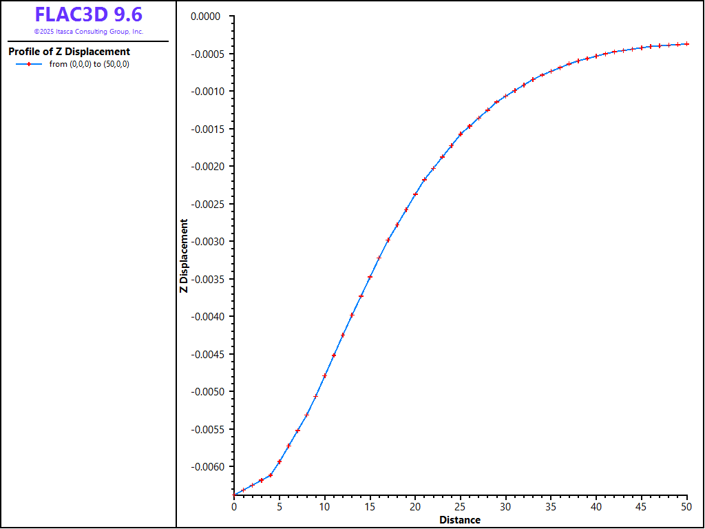
Figure 4: Final settlement profile.
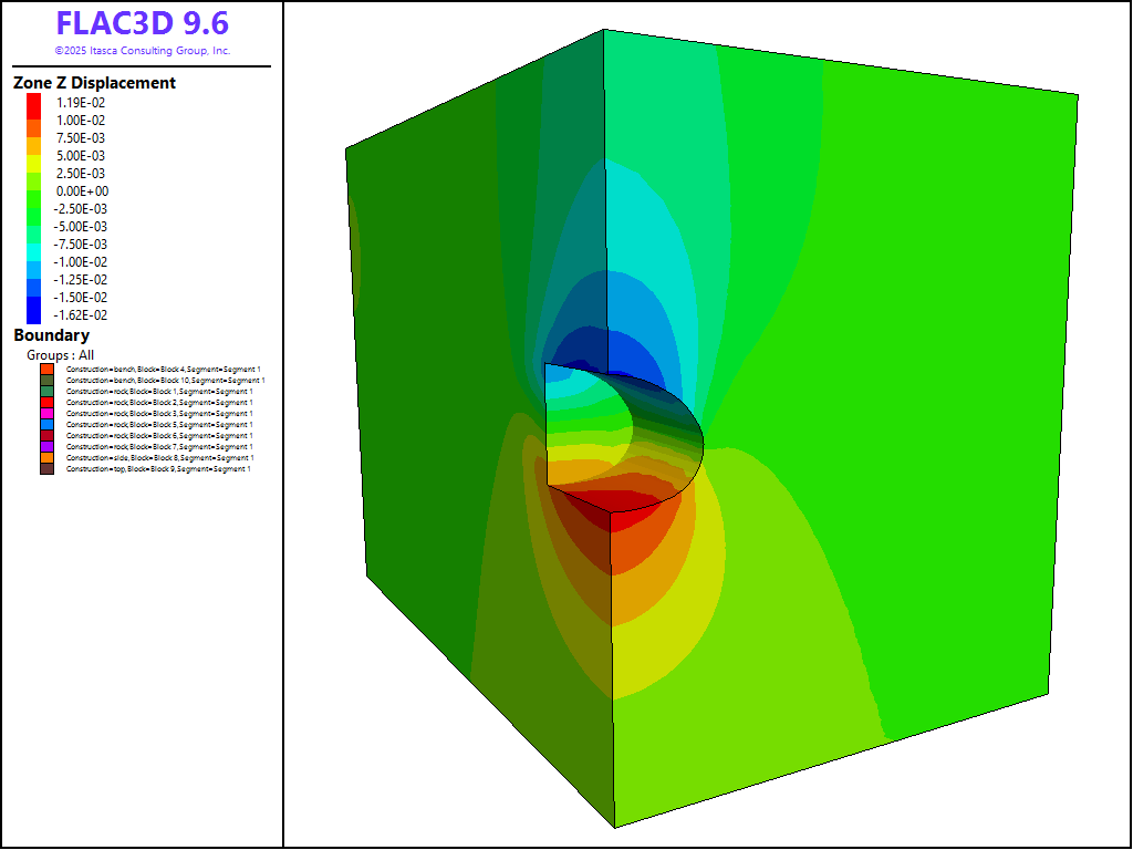
Figure 5: Magnitude of displacement after all excavations.
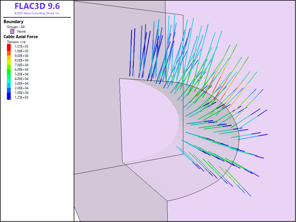
Figure 6: Final axial forces in rockbolts (cables).
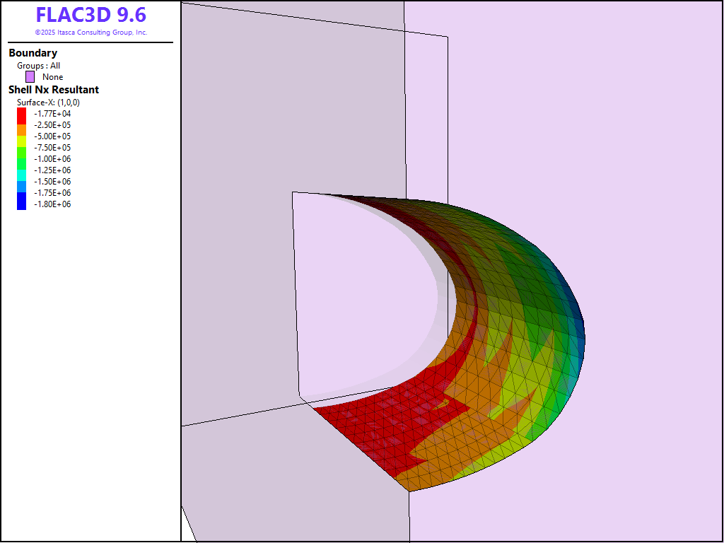
Figure 7: Final axial stress resultants in shotcrete lining (shells).
Moment-Thrust Diagram
Figure 8 shows a moment-thrust diagram for the shell elements (shotcrete lining) after the final excavation stage. To create this figure, the strength properties of the shell need to be specified under the Property attribute for the plot item. Use these values to create the plot shown:
Compression strength |
10e6 |
Tension strength |
1e6 |
Area |
0.3 |
Then check click the + symbol next to all of the shell groups and check the boxes to show Safety Factors of 1, 1.1, and 1.2. It can be seen that all of the shell elements are within a Safety Factor of 1.1. The specific beam IDs can be determined by hovering over the specific points and observing the contents of the information box. The low Safety Factors for these points suggest extra support may be required here.
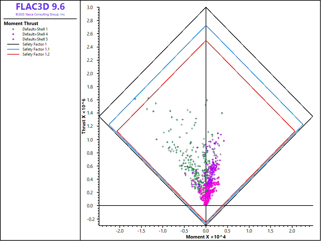
Figure 8: Moment-thrust diagram (tensile yield strength = 1 MPa, compressive yield strength = 10 MPa) for shotcrete liner at the last excavation stage.
Data Files
inistress.dat
zone face skin
zone face apply velocity-x 0 range group 'West' or 'East'
zone face apply velocity-y 0 range group 'North' or 'South'
zone face apply velocity 0 0 0 range group 'Bottom'

zone cmodel assign mohr-coulomb
zone property density 2700 bulk 5.555e8 shear 4.166e8 ...
    friction 33 cohesion 25.0e3 tension 25.0e3

zone initialize-stresses ratio 0.5

model solve
model save 'inistress.sav'
excavate.dat
zone gridpoint initialize displacement 0 0 0
zone gridpoint initialize velocity 0 0 0

fish define createShell(grp,ymin,ymax)
    if grp == 'side' then
        command
            structure shell create by-zone-face id 1 range group 'side-rock' position-y [ymin] [ymax]
            structure shell create by-zone-face id 2 range group 'top-side' position-y [ymin] [ymax]
            structure shell create by-zone-face id 3 range group 'bench-side' position-y [ymin] [ymax]
        endcommand
    else if grp == 'top' then
        command
            structure shell create by-zone-face id 4 range group 'top-rock' position-y [ymin] [ymax]
        endcommand
    else if grp == 'bench' then
        command
            structure shell create by-zone-face id 5 range group 'bench-rock' position-y [ymin] [ymax]
        endcommand
    else
        system.error = 'invalid group'
    endif

    command
        structure shell cmodel assign elastic
        structure shell property young 5.5e9 poisson 0.2 thickness 0.3
    endcommand
end

fish define createBolts(offset,cgrp,rgrp)
    local oset = vector(0,offset,0)
    command
        structure cable import from-sketch 'rockbolts' offset [oset] segments 6 group [cgrp] range group [rgrp]
        structure link attach x rigid y rigid z rigid range group 'Cable Begin'
        structure cable group 'grout=ungrouted' range geometry-distance 'tunnel' gap 3.5 group [cgrp]
        structure cable property cross-sectional-area 5e-4 young 2e11 yield-tension 5e5 ...
            grout-stiffness 1.5e10 grout-cohesion 8e5 range group [cgrp]
        structure cable property grout-cohesion 0 range group [cgrp] group 'ungrouted'
    endcommand
end

fish define Step1(grp,ymin,ymax,shellID)
    if grp # 'side'
        command
            structure shell delete range id [shellID] position-y [ymin] [ymax]
        endcommand
    endif
    command
        zone null range group [grp] position-y [ymin] [ymax]
        model solve
    endcommand
end

fish define Step2(grp,idx,ymin,ymax,offset)
    local cgrp = grp + '2' + 'idx'
    local rgrp = grp + 'bolts'
    command
        zone null range group [grp] position-y [ymin] [ymax]
    endcommand
    if grp # "bench"
        createBolts(offset,cgrp,rgrp)
    endif
    command
        model solve
    endcommand
end

fish define Step3(grp,idx,ymin,ymax,offset,symin,symax)
    local cgrp = grp + '3' + idx
    local rgrp = grp + 'bolts'
    command
        zone null range group [grp] position-y [ymin] [ymax]
    endcommand
    if grp # "bench"
        createBolts(offset,cgrp,rgrp)
    endif
    createShell(grp,symin,symax)

    command
        ; this is necessary on the symmetry planes
        structure node fix velocity-y range position-y 0
        structure node fix rotation-x range position-y 0
        structure node fix rotation-z range position-y 0

        structure node fix velocity-x range position-x 0
        structure node fix rotation-y range position-x 0
        structure node fix rotation-z range position-x 0

        model solve
    endcommand
end

; ------------------------------- ;
; Excavate 0-3 m
; ------------------------------- ;
[Step1('side',0,1,99)]
[Step2('side','a',1,2,0.5)]
[Step3('side','a',2,3,1.5,0,1)]

[Step1('top',0,1,2)]
[Step2('top','a',1,2,0.5)]
[Step3('top','a',2,3,1.5,0,1)]

[Step1('bench',0,1,3)]
[Step2('bench','a',1,2,0.5)]
[Step3('bench','a',2,3,1.5,0,1)]

structure shell recover surface 0 1 0
structure shell recover resultants
model save 'excavate_01.sav'

; ------------------------------- ;
; Excavate 3-6 m
; ------------------------------- ;
[Step1('side',3,4,99)]
[Step2('side','b',4,5,3.5)]
[Step3('side','b',5,6,4.5,1,4)]

[Step1('top',3,4,2)]
[Step2('top','b',4,5,3.5)]
[Step3('top','b',5,6,4.5,1,4)]

[Step1('bench',3,4,3)]
[Step2('bench','b',4,5,3.5)]
[Step3('bench','b',5,6,4.5,1,4)]

structure shell recover surface 0 1 0
structure shell recover resultants
model save 'excavate_02.sav'

; ------------------------------- ;
; Excavate 6-9 m
; ------------------------------- ;
[Step1('side',6,7,99)]
[Step2('side','c',7,8,6.5)]
[Step3('side','c',8,9,7.5,4,7)]

[Step1('top',6,7,2)]
[Step2('top','c',7,8,6.5)]
[Step3('top','c',8,9,7.5,4,7)]

[Step1('bench',6,7,3)]
[Step2('bench','c',7,8,6.5)]
[Step3('bench','c',8,9,7.5,4,7)]

structure shell recover surface 0 1 0
structure shell recover resultants
model save 'excavate_03.sav'

; ------------------------------- ;
; Excavate 9-12 m
; ------------------------------- ;
[Step1('side',9,10,99)]
[Step2('side','d',10,11,9.5)]
[Step3('side','d',11,12,10.5,7,10)]

[Step1('top',9,10,2)]
[Step2('top','d',10,11,9.5)]
[Step3('top','d',11,12,10.5,7,10)]

[Step1('bench',9,10,3)]
[Step2('bench','d',10,11,9.5)]
[Step3('bench','d',11,12,10.5,7,10)]

structure shell recover surface 0 1 0
structure shell recover resultants
model save 'excavate_04.sav'
Endnotes
⇐ Assessment of Fault Slip Potential from Sill Pillar Mining | Smooth Circular Footing on an Associated Mohr-Coulomb Material (FLAC2D) ⇒
| Was this helpful? ... | Itasca Software © 2026, Itasca | Updated: Feb 07, 2026 |
