Lined Tunnel Construction in Saturated Ground (FLAC2D)
Problem Statement
Note
The project file for this example is available to be viewed/run in FLAC2D.The project’s main data file is shown at the end of this example.
A circular tunnel with an excavated radius of 6 m, and with its center at a depth of 65 m below the surface, is constructed in saturated ground. The pre-construction water table is at a depth of 5 m below the surface. The ground is dewatered during the construction phase. The tunnel is supported by a temporary shotcrete liner, which is installed while the tunnel excavation advances, and a final cast-in-place 0.4 m-thick concrete liner. The analysis is required to determine the forces and moments that develop in the concrete liner both when the water level returns to its original elevation and when, at a later time, the temporary shotcrete liner loses its strength.
The construction sequence considered in this analysis is divided into six stages.
Before construction begins, the water table is lowered to approximately 10 m below the tunnel invert using dewatering wells. The initial in-situ stress ratio, Ko, is 0.5 for the unsaturated state.
The excavation begins, and the tunnel advancement produces tunnel closure corresponding to a 30% relaxation of the modulus of the excavated material before the shotcrete liner is installed.
The shotcrete is installed, the tunnel is advanced to produce 100% relaxation, and load develops in the shotcrete. Note that the shotcrete is sufficiently porous such that it provides negligible resistance to fluid flow when the original water table is restored.
A permanent cast-in-place concrete liner is then placed inside the shotcrete-lined tunnel. A plastic waterproof membrane covers the concrete liner; the concrete plus membrane is impermeable.
After the concrete liner is installed, the dewatering wells are stopped, and the water rises to the original level. Pore pressures are reestablished throughout the ground and the outer liner, but fluid does not penetrate past the impermeable inner liner. The water exerts a pressure in the “gap” between the two liners; this pressure causes axial forces to develop within the liners.
Finally, the shotcrete liner degrades over time, and the ground relaxes into the inner liner.
Figure 1 illustrates the construction sequence that is simulated in the FLAC2D analysis. The figure also lists the rock, shotcrete and concrete liner properties assumed for the analysis.
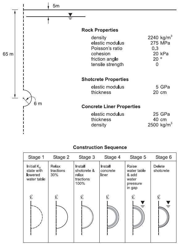
Figure 1: Conditions and sequence for the lined tunnel construction.
Model Construction
The model is built in Sketch as follows.
Create a new Sketch set. Draw a rectangle (corner-corner) from 0,-80 to 120,65.
Draw a horizontal line from 0,60 to 120,60.
Draw a circle using Center-Radius. Set the center to 0,0 and the radius to 6.
Delete the sections of the circle outside of the rectangle.
From the meshing drop-down, select Auto-size. Set the zone length to 4 and the minimum number of zones per edge to 2.
Click on the two segments of the circle and set the number of zones to 16.
Click on the vertical line that goes from the top of the circle to the bottom, and set the number of zones to 20.
Click on the vertical line above the tunnel and set the number of zones to 20 and the ratio to 1.1.
Click on the vertical line below the tunnel and set the number of zones to 22 and the ratio to 1.1.
Go to Meshing Parameters, and check the box to Create unstructured meshes only. Then click “Mesh Now”. The model should appear as shown.
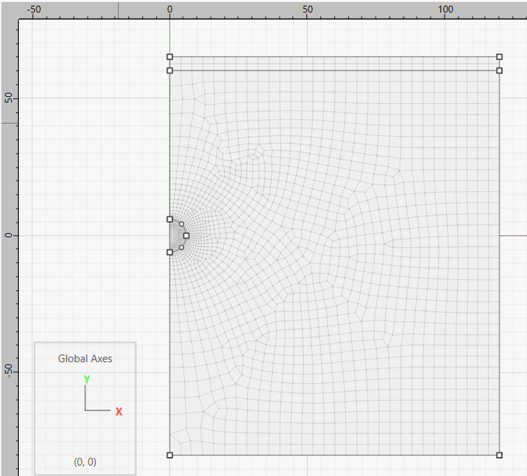
Figure 2: Model geometry created in Sketch workspace.
Select the two arcs that define the tunnel edge and set their group name to “Tunnel Wall”.
Select the zones inside the tunnel and set the group name to “Tunnel”.
Select the zones that make up the top layer and set the group name to “Ground”.
Generate the zones
Modeling Procedure
The six construction stages are simulated as separate steps in the FLAC2D analysis. Each step is described in the following sections. The model is created using FLAC2D Sketch tool as described above.
Step 1: Initial State with Lowered Water Table
The model creation takes advantage of the problem symmetry, as shown in Figure 2. Figure 3 shows the standard boundary conditions that can be in this example. The left boundary is a line of symmetry, and the right boundary is fixed from movement in the \(x\)-direction. The top boundary is a free surface, and the bottom boundary is fixed from movement in both the \(x\)- and \(y\)-directions. Figure 4 shows a close-up view in the vicinity of the tunnel, in which finer zoning is created.
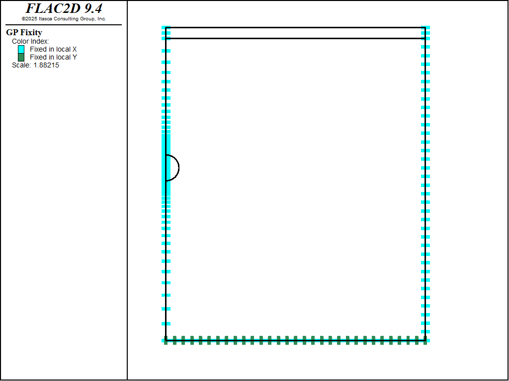
Figure 3: Assigned boundary conditions.

Figure 4: Close-up view of tunnel region.
The material properties for the rock are listed in Figure 1, and the rock density is considered to be the unsaturated value. The initial stress state is specified with the zone initialize-stress ratio 0.5 command assuming that no water is present. The xx-stress and zz-stress components are computed based on the lateral stress ratio,Ko = 0.5. The initial vertical stress distribution is shown in Figure 5.
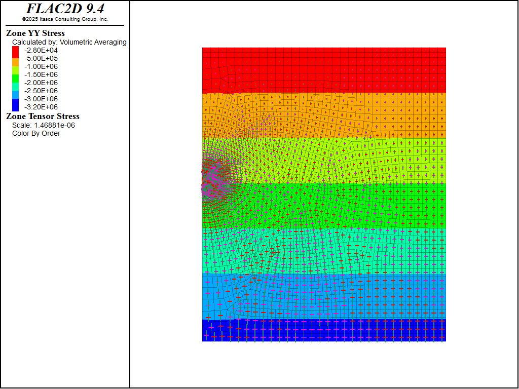
Figure 5: Vertical stress contours and stress tensors at initial state.
Step 2: Tunnel Excavation with 30% Relaxation of Tunnel
The zone relax excavate command is applied to all zones inside the tunnel. The modulus of the excavation area is gradually reduced to 70% of its initial value. The keyword minimum is used to specify the minimum reduction factor of 0.7. The tunnel closure is monitored as a history during the excavation. The FISH function named VERT_CLOSURE is executed to monitor the vertical closure/opening, calculated as the difference between vertical displacement at the crown and invert of the tunnel. The horizontal closure is also monitored by taking a history of the \(x\)-displacement at a gridpoint along the tunnel boundary.
Step 3: Install Shotcrete and Relax Tunnel 100%
The tunnel is now relaxed completely. Before this, beam elements are added representing the shotcrete. The structural nodes are attached directly to the grid, as shown in Figure 6. The model is then brought to equilibrium. Note that the weight of the shotcrete is neglected for this example. Because only one-half of the beam is modeled, the nodes along the line of symmetry must be fixed from translation in the \(x\)-direction and from rotation.
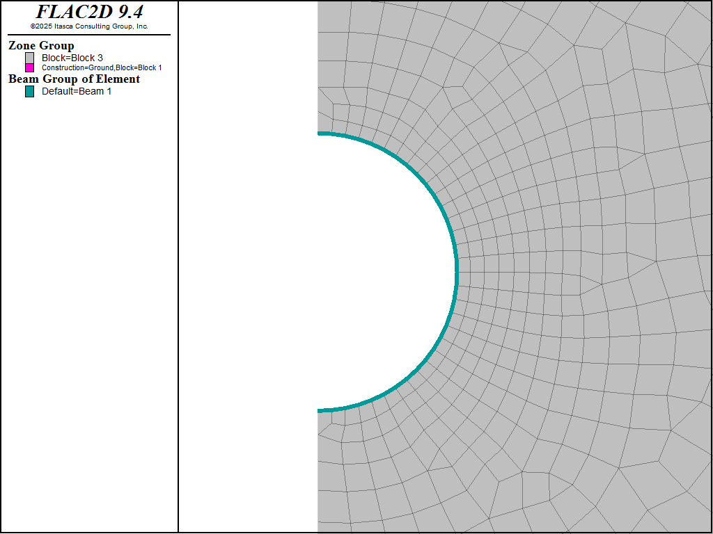
Figure 6: Shotcrete liner installed as beam elements attached to tunnel boundary.
Figure 7 displays the vertical and horizontal closure histories for the tunnel. The total vertical closure is approximately 9.0 cm after 100% relaxation. The axial forces that develop in the shotcrete after total relaxation are shown in Figure 8. The maximum force corresponds to an axial stress of approximately 23 MPa.
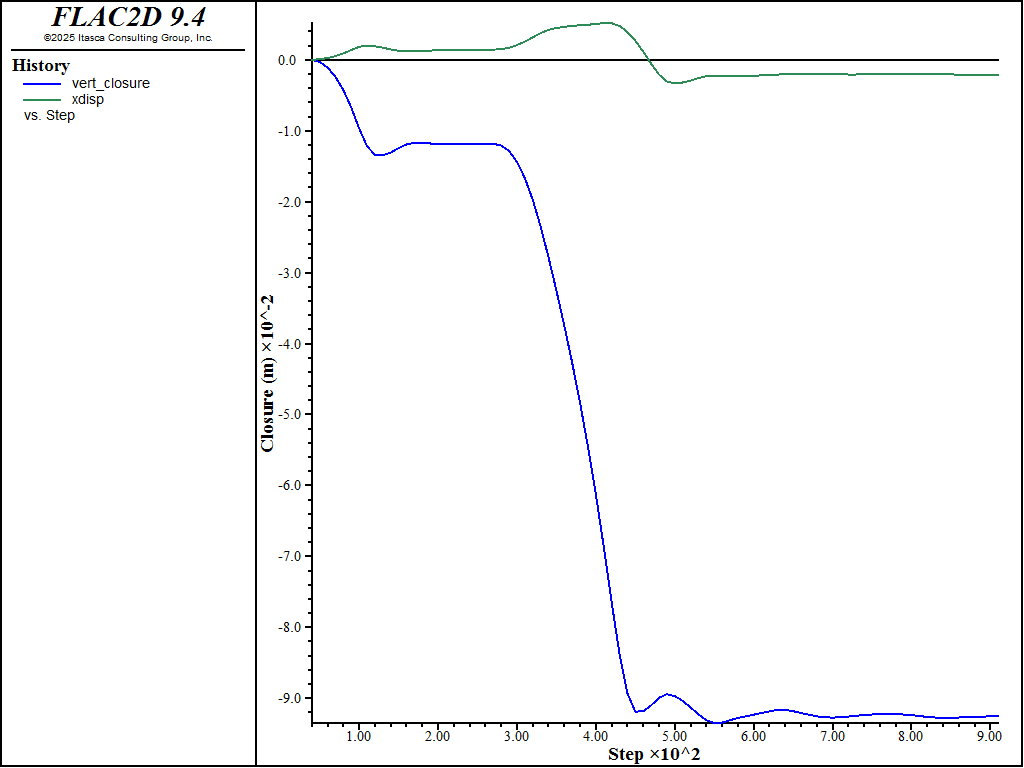
Figure 7: Vertical and horizontal closures around tunnel.
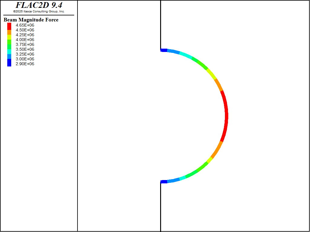
Figure 8: Axial forces in shotcrete after 100% relaxation of tunnel.
Step 4: Install Concrete Liner
The cast-in-place concrete liner is installed in Step 4. The FISH function named “MoveLiner” is used to move the liner nodes away from the tunnel boundary to create an initial gap of 1 cm between the liner elements and the grid. The translation and rotation fixity conditions for the concrete-liner nodes along the center line must also be set. This satisfies the symmetry condition as done previously for the shotcrete liner. The model is stepped again to an equilibrium state. The concrete liner settles onto the grid at the invert of the tunnel, and normal stresses develop along the boundary between the soil and the liner, as shown in Figure 9. The coupling spring normal stress plot is used to clearly show those segments in contact.
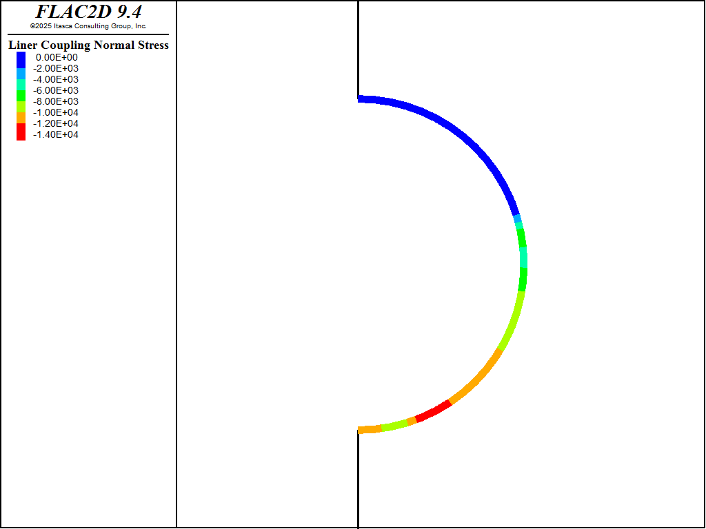
Figure 9: Normal stresses along liner coupling spring after concrete liner settles onto grid at tunnel invert.
Step 5: Reestablish Water Table
The water level is raised to the original elevation at y = 60 m in this model by using zone gridpoint pore-pressure head command, as shown in Figure 10. When the water level is raised, the water is reestablished throughout the ground and the permeable shotcrete liner, but not in the impermeable concrete liner. Thus, the water exerts a pressure in the gap between the two liners. The pressure acts on both the inner concrete liner and the outer shotcrete liner. The pressure applied to the shotcrete liner is applied using the zone face apply stress-normal command.

Figure 10: Pore-pressure distribution corresponding to raising the water table to y = 60 m.
In order to apply a pressure to the inner concrete liner, it is necessary to write a FISH function that calculates the forces at the liner nodes that correspond to the water pressure. The function apply_gap_pressure performs this operation. This function accesses liner-element variables associated with the concrete liner. The \(x\)- and \(y\)-direction forces calculated corresponding to the water pressure at the depth of each liner node along the concrete liner. One input parameter is required for this function (water table \(y\) coordinate). After apply_gap_pressure is executed, The model is stepped again to an equilibrium state.
The vertical distance between the crown and invert increases by approximately 1.4 cm due to the water pressure gradient, as shown in Figure 11. The resulting axial forces in the liners are shown in Figure 12. The moment distribution in the concrete liner is displayed in Figure 13.
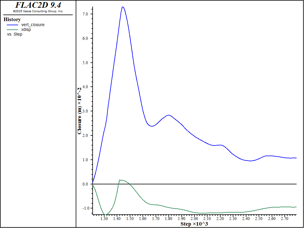
Figure 11: Tunnel closure/opening after raising water table.
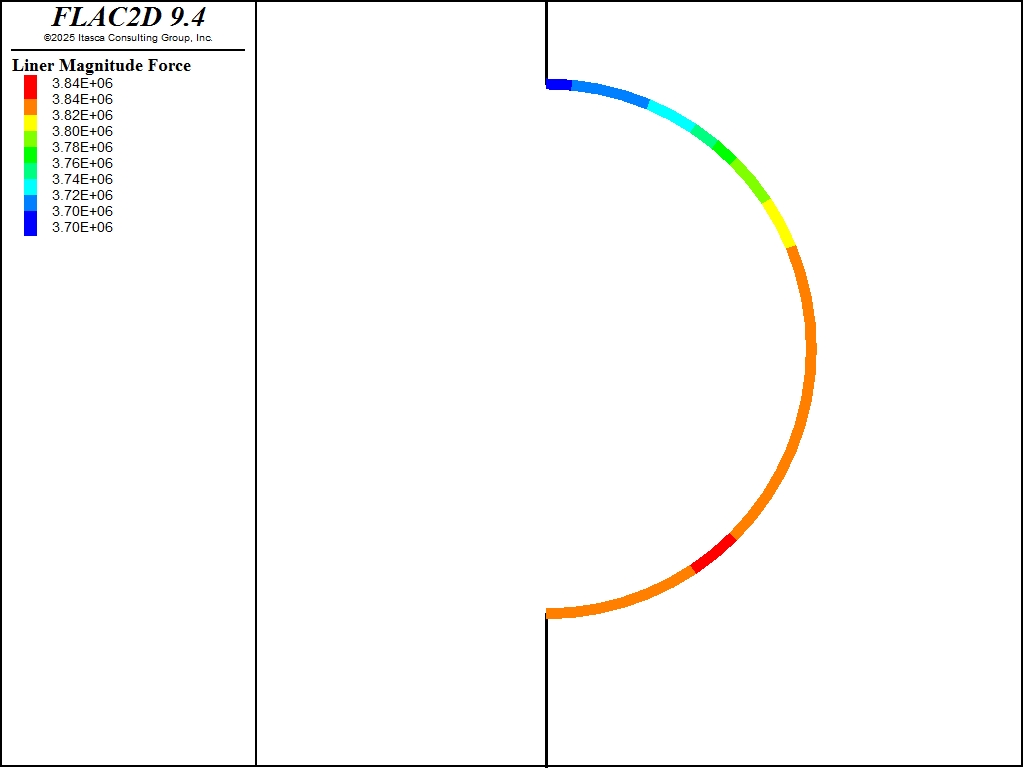
Figure 12: Axial forces in liners after raising water table.
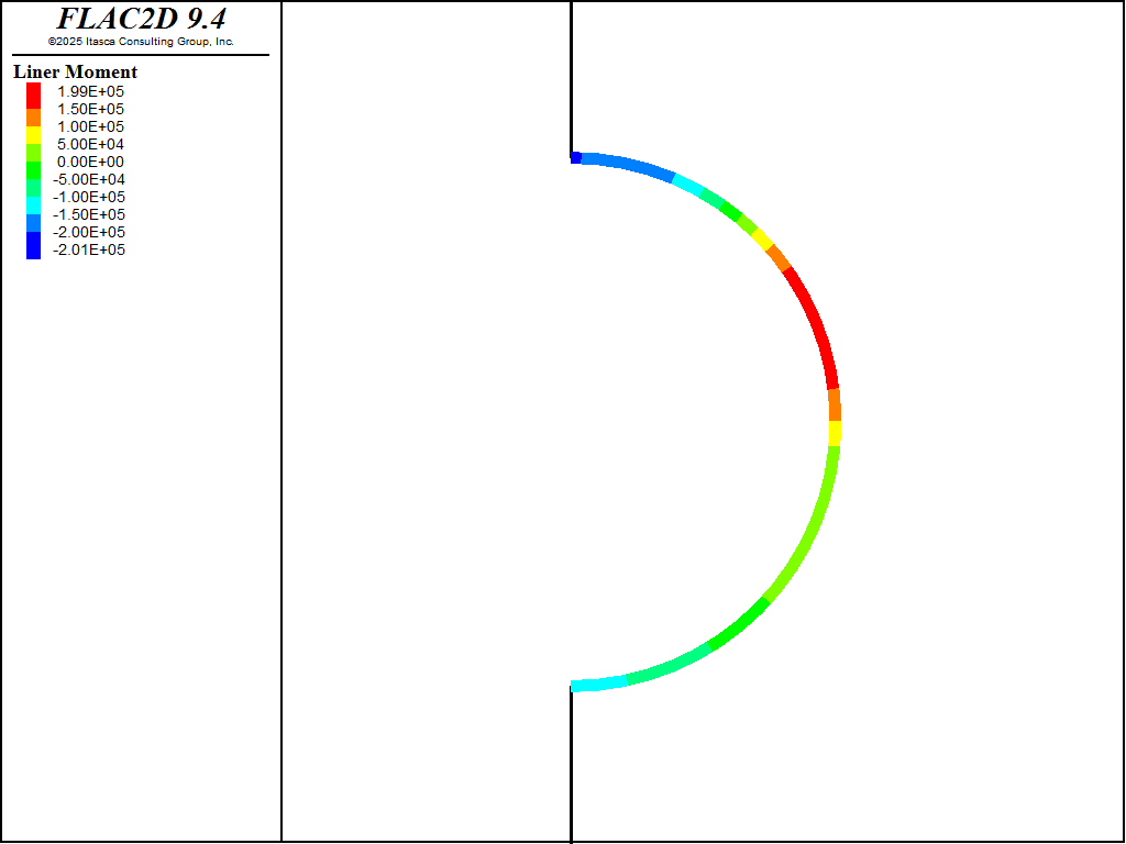
Figure 13: Moments in concrete liner after raising water table.
Step 6: Delete Shotcrete Liner
In the last step of this analysis, the shotcrete is deleted to represent the degradation of the liner. The final axial load in the concrete liner after the shotcrete is deleted is shown in Figure 14. The maximum force corresponds to an axial stress of approximately 18 MPa.
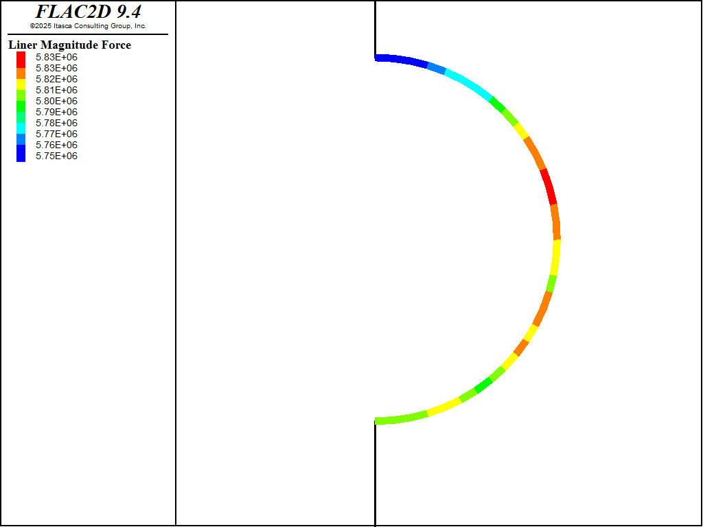
Figure 14: Axial force in concrete liner after deleting shotcrete liner.
References
Panet, M. “Time-Dependent Deformations in Underground Works,” in Proceedings of the 4th ISRM Congress (Montreux), Vol. 3, pp. 279-289. Rotterdam: A. A. Balkema and the Swiss Society for Soil and Rock Mechanics (1979).
Data Files
initial.dat
model new
model restore 'mesh'

model configure fluid-flow
model large-strain off
model title 'Lined Tunnel'

; ====== mechanical properties =======
zone cmodel assign mohr-coulomb

zone property density 2240 young 275e6 poisson 0.30 friction 20 ...
              cohesion 2e4
model gravity 10

; ===== boundary conditions =======
zone face skin
zone face apply velocity-x 0 range group 'East' or 'West'
zone face apply velocity 0 0 range group 'Bottom'
; Initialize stress, with different ratios in the layers
zone initialize-stresses ratio 0.5

; Solve
model solve-static elastic
model save 'initial'
relax30.dat
model restore 'initial'

[topgp = gp.near(0,6)]
[bottomgp = gp.near(0,-6)]

fish define vert_closure
   vert_closure = gp.dis.y(bottomgp) - gp.dis.y(topgp)
end

fish history name 'vert_closure' vert_closure
zone history name 'xdisp' displacement-x position 6.0,0.0

zone relax excavate name 'relax30' minimum 0.7 range group 'Tunnel'

model solve-static
model save 'relax30'
relax100.dat
model restore 'relax30'

zone relax modify 'relax30' minimum 0.0 ; modify the relax condition,
                                        ; don't add a new one

; interal keyword to select internal faces
; Young's modulus scaled to make beams behave like liners
structure beam create by-zone-face internal range group 'Tunnel Wall'
structure beam property young [5e9/(1.0-0.2^2)] poisson 0.2 ...
                        cross-sectional-area 0.2 ...
                        moi=6.667E-4

structure node fix velocity-x rotation range position-x 0

model solve-static
model save 'relax100'
concreteliner.dat
model restore 'relax100'

structure liner create by-zone-face group 'Concrete' range group 'Tunnel Wall'

structure liner cmodel assign elastic

structure liner property young 2.5e10 poisson 0.2 cross-sectional-area 0.4 ...
                      moi 0.005333 density 2500

structure liner property coupling-stiffness-normal 4e9 ...
             coupling-stiffness-shear 4e9 coupling-yield-normal 0 ...
             coupling-cohesion-shear 0 coupling-cohesion-shear-residual 0 ...
             coupling-friction-shear 30.0

; this is required because we will move the liner away from the sopil surface
; but we don't want to lose the links
structure link tolerance-contact 0.4
;structure liner property slide on slide-tolerance 0.4 ; for large-strain on

model solve-static cycles 0 ; to get liner node local coord system

; node coordinate system at the symmetry nodes does not exactly
;  line up with global x and y because of missing left part of liner
; We need to line them up so we can fix the degrees of freedom
structure node system-local x 1 0 y 0 1 range component-id 38 ; bottom
structure node system-local x -1 0 y 0 -1 range component-id 35 ; top
structure node fix system-local range component-id-list 35 38

structure node fix velocity-x rotation range component-id-list 35 38

; set up a 1 cm gap between concrete liner and tunnel wall
fish define setup_gap
  loop foreach local link struct.link.list
    if struct.link.isgroup(link,'Concrete')
      ; gap is in local y direction
      struct.link.model.gap(link,2) = true
      struct.link.model.gap.pos(link,2) = 0.01
    endif
  end_loop
end
[setup_gap]

;; you could do it this way instead
;fish define MoveLiner
;  loop foreach local selnode struct.node.list
;    if struct.node.isgroup(selnode,'Concrete')
;      ; second degree of freedom is local y (perpendicular to liner)
;      local value = 0.01*struct.node.system.local(selnode,2)
;      command
;        structure node initialize position [value] add ...
;          range component-id [struct.node.id.component(selnode)]
;      endcommand
;    endif
;  endloop
;end
;[MoveLiner]

model solve-static
model save 'concreteliner'
raisingwater.dat
model restore 'concreteliner'

zone fluid unsaturated cutoff 0
zone fluid property mobility-coefficient 1e-10 porosity 0.3
zone fluid-density 1000
zone gridpoint pore-pressure head 60
zone gridpoint fix pore-pressure range group 'East'

zone fluid steady-state

model save 'water'
gappressure.dat
model restore 'water'

zone face apply stress-normal -6.6e5 gradient 0,1.0e4 ...
          range group 'Tunnel Wall' position-y -6.0 6.0

program call 'applygappressure.fis'
[apply_gap_pressure(60.0)]

zone gridpoint initialize displacement (0,0)
zone gridpoint initialize velocity (0,0)

history purge
model solve-static
model save 'gappressure'
deleteshotcrete.dat
model restore 'gappressure'
structure beam delete

model solve-static
model save 'deleteshotcrete'
| Was this helpful? ... | Itasca Software © 2024, Itasca | Updated: Jun 07, 2025 |
