Examples • Example Applications
Displacements near the Face of an Advancing Shaft (FLAC2D)
Problem Statement
Note
The project file for this example is available to be viewed/run in FLAC2D.The project’s main data file is shown at the end of this example.
A circular shaft is excavated in chalk and lined with monolithic precast concrete segments. The aim of this exercise is to determine the displacements that take place before the lining is installed. This type of information can then be used to enable a two-dimensional plane-strain analysis to include the effect of shaft or tunnel advancement on relaxation of shaft or tunnel loads.
For this example, the shaft’s diameter is 5.44 m, and the thickness of the lining is 22 cm. The excavation increments are 2 m long, and after each round a 2 m precast concrete segment is placed right up to the face. Figure 1 shows a cross-section view of the process.
In reality, the chalk exhibits time-dependent behavior associated with creep. The analysis presented here is limited to the elastic response, which accounts for the closure near the face. The following properties are used.
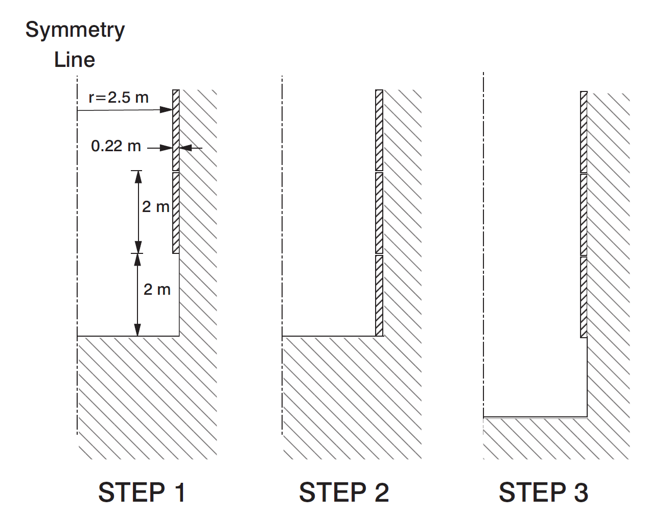
Figure 1: Problem geometry and excavation steps.
Chalk |
|
Density (kg/m3) |
2350 |
Young’s modulus (MPa) |
600 |
Shear modulus (MPa) |
360 |
Equivalent thickness (m) |
1.26 |
Concrete Liner |
|
Density (kg/m3) |
2500 |
Bulk modulus (GPa) |
14 |
Shear modulus (GPa) |
8.4 |
The in-situ stress state is considered to be hydrostatic, with \(\sigma_xx\) = \(\sigma_yy\) = \(\sigma_zz\) = 1.5 MPa. Panet (1979) published an expression relating shaft closure of an unsupported shaft to the distance to the shaft face. The expression provides a starting point for this example. The solution calculates radial displacements, ur , at the shaft circumference:
with
where R = unlined shaft radius; \(h_o\) ∼= 1/3; \(\sigma_0\) = in-situ pressure; G = shear modulus; and |y|= distance to the face (positive in the direction of the advancing face).
Two analyses are performed for the advancing shaft:
(1) the unlined shaft is modeled and the results compared to Panet’s (1979) solution; and (2) the effect of the lining is studied.
Modeling Procedure
Because the axis of the shaft is an axis of radial symmetry, an axisymmetric elastic model is used in this example. The FLAC2D model has dimensions 30 m by 60 m, and contains 2890 zones. In order to limit the effect of the boundary condition, 30 meters of shaft have been modeled (6 diameters).
For the unlined case, the excavation of the 30 meters has been modeled in only one step (see “UNLINED.DAT”). For the lined case, the excavation sequence is followed. The FISH function excav in “LINED.DAT” simulates the excavation sequence. Figure 2 show the zone geometry before excvavation.
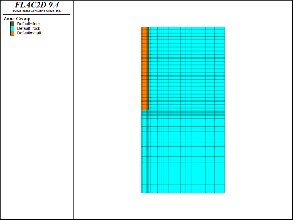
Figure 2: Zone geometry.
Results
For the analysis of the unlined shaft, the radial displacements, ur , calculated at the shaft circumference closely match Panet’s solution. Figure 3 compares the radial displacements as a function of the distance to the face obtained from FLAC2D with Panet’s solution.
For the lined shaft analysis, the radial displacements that take place at the shaft interface with the precast liner are plotted in Figure 4. The displacements are approximately 60% of those with no liner. The jagged shape is due to the uneven radial displacement of the unsupported span, which is partially confined at both ends (last ring of lining and shaft’s face) and relatively free to move in the middle.
Figure 5 shows a magnified grid plot for the unlined shaft, while Figure 6 shows the same plot for the lined shaft. The jagged shape of the deformed liner is also evident in the second plot.
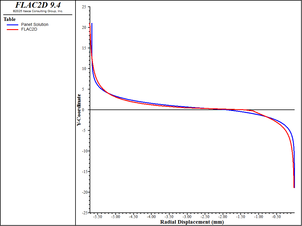
Figure 3: Comparison of radial displacements (mm) as a function of the distance to the face (m) for the unlined shaft.
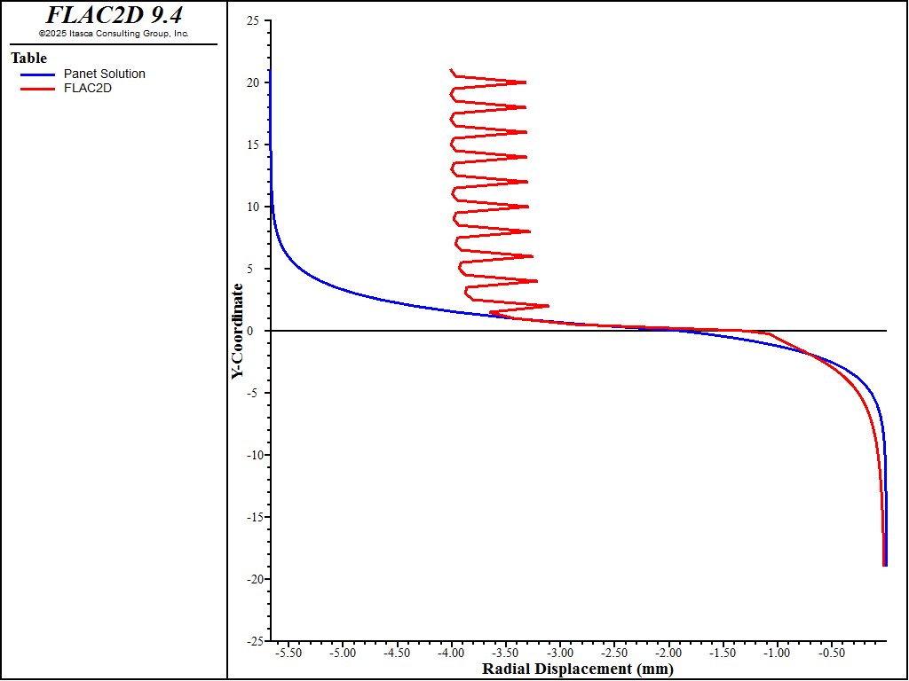
Figure 4: Comparison of radial displacements (mm) as a function of the distance to the face (m) for the lined shaft.
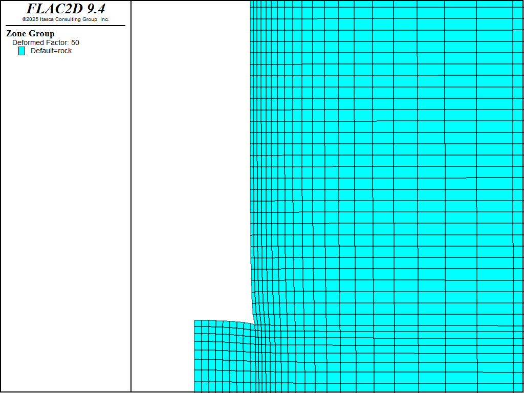
Figure 5: Deformed grid for the unlined shaft (magnification factor = 50).
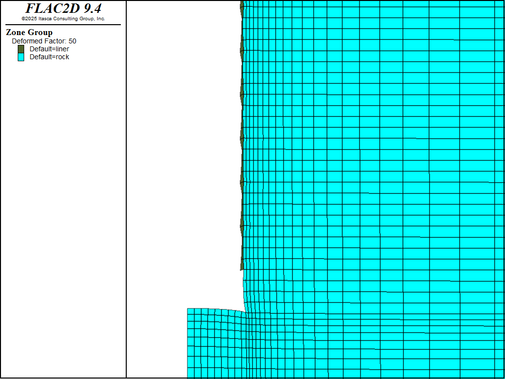
Figure 6: Deformed grid for the lined shaft (magnification factor = 50).
References
Panet, M. “Time-Dependent Deformations in Underground Works,” in Proceedings of the 4th ISRM Congress (Montreux), Vol. 3, pp. 279-289. Rotterdam: A. A. Balkema and the Swiss Society for Soil and Rock Mechanics (1979).
Data Files
Unlined.dat
;---------------------------------------------------------------------
;Displacements near the Face of an Advancing Shaft

;---------------------------------------------------------------------
model new
model large-strain off
model configure axisymmetry

; Create zones

; shaft
zone create2d quadrilateral point 0 0,-30 point 1 2.5,-30 point 2 0,0 ...
  size 8 25 ratio 1 0.9 group 'rock'
zone create2d quadrilateral point 0 0,0 point 1 2.5,0 point 2 0,30 ...
  size 8 60 group 'shaft'

; liner
zone create2d quadrilateral point 0 2.5,-30 point 1 2.72,-30 point 2 2.5,0 ...
  size 1 25 ratio 1 0.9 group 'rock'
zone create2d quadrilateral point 0 2.5,0 point 1 2.72,0 point 2 2.5,30 ...
  size 1 60 group 'liner'

; rock
zone create2d quadrilateral point 0 2.72,-30 point 1 30,-30 point 2 2.72,0 ...
  size 25 25 ratio 1.15 0.9 group 'rock'
zone create2d quadrilateral point 0 2.72,0 point 1 30,0 point 2 2.72,30 ...
  size 25 60 ratio 1.15 1 group 'rock'

;zone import 'out'

; Assign constitutive model and properties
zone cmodel assign elastic
zone property bulk 6.e8 shear 3.6e8 density 2350

; initial conditions and boundary conditions
zone face skin
zone initialize stress xx -1.5e6 yy -1.5e6 zz -1.5e6
zone face apply stress-xx -1.5e6 range group 'East'
zone face apply velocity-y 0 range group 'Bottom' or 'Top'

; monitoring
zone history name 'unbal' unbalanced-force
zone history name 'disp1' displacement-x position (2.72,0)
zone history name 'disp2' displacement-x position (2.72,25.3)

model save 'initial'

; excavate and solve
zone null range group 'shaft' or 'liner'
model solve-static

zone gridpoint group 'bc' range position-x 2.72 position-y  -21 21
[gplist = list(gp.list)(gp.isgroup(::gp.list,"bc"))]

program call 'panet.fis'

model save 'unlined'
Lined.dat
;---------------------------------------------------------------------
;Displacements near the Face of an Advancing Shaft

;---------------------------------------------------------------------
model restore 'initial'

model solve-static

; excavate in 2 m segments with liner 2 m behind
fish define excav
  local zlen = 2.0
  local ypos = 30.0
  loop local k (1,15)
    local yy1=ypos-zlen
    local yy2=ypos
    local yy3=ypos+zlen
    command
      zone null range group 'shaft' or 'liner' position-y ([yy1],[yy2])
      zone cmodel assign elastic range group 'liner' position-y ([yy2],[yy3])
      zone property bulk 14e9 shear 8.4e9 density 2500 range ...
                group 'liner' position-y ([yy2],[yy3])
      model solve-static
    end_command
    ypos=yy1
  end_loop
end
[excav]

; identify gridpoints along the shaft
zone gridpoint group 'bc' range position-x 2.72 position-y  -21 21
[gplist = list(gp.list)(gp.isgroup(::gp.list,"bc"))]

program call 'panet.fis'

model save 'lined'
⇐ Stresses around a Pressurized Concrete Tunnel (FLAC2D) | Analysis of a Concrete Diaphragm Wall (FLAC2D) ⇒
| Was this helpful? ... | Itasca Software © 2024, Itasca | Updated: Jun 07, 2025 |
